Power Architecture
SoC has an advanced Power Management Controller (PMC), which can flexibly power up different power domains of the chip, to achieve the best balance between chip performance and power consumption.
There are generally three main power domains in the digital system of the SoC: AON, SYSON, and SOC.
Functions in different power domains will be turned off differently in different power-saving modes.


Note
The RTC power domain is unique to the RTL8721F. Throughout all the operation modes described in this document, the RTC and AON domains maintain identical working states. As such, no distinction is made between them.
Power-Saving Mode
We supports two low-power modes, which are sleep mode and deep-sleep mode. The deep-sleep mode turns off more power domains than the sleep mode, so it has lower power consumption.
Tickless is a FreeRTOS low power feature, which just gates the CPU (no clock or power be turned off) when it has nothing to do. Sleep mode flow and deep-sleep mode flow are based on Tickless.
The following table explains power-saving related terms.
Mode |
AON domain |
SYSON domain |
SOC domain |
Description |
|---|---|---|---|---|
Tickless |
ON |
ON |
ON |
|
Sleep |
ON |
ON |
|
|
Deep-Sleep |
ON |
OFF |
OFF |
|
Tickless for FreeRTOS
The FreeRTOS supports a low-power feature called Tickless. It is implemented in an idle task which has the lowest priority. That is, it is invoked when there is no other task under running.
Note
configUSE_TICKLESS_IDLE must be enabled for power-saving application because sleep mode flow is based on Tickless.
Unlike the original FreeRTOS, We don’t wake up based on the xEpectedIdleTime.

FreeRTOS Tickless in an idle task
The figure above shows idle task code flow. In idle task, it will check sleep conditions (wakelock, sysactive_time, details in Section Wakelock APIs and pmu_set_sysactive_time) to determine whether needs to enter sleep mode or not.
If not, the CPU will execute an ARM instruction WFI (wait for interrupt) which makes the CPU suspend until the interrupt happens. Normally systick interrupt resumes it. This is the software Tickless.
If yes, it will execute the function
freertos_pre_sleep_processing()to enter sleep mode or deep-sleep mode.
Note
Even FreeRTOS time control like software timer or vTaskDelay is set, it still enters the sleep mode if meeting the requirement as long as the idle task is executed.
Wi-Fi Power Saving
IEEE 802.11 power save management allows the station to enter its own sleep state. It defines that the station needs to keep awake at a certain timestamp and enter a sleep state otherwise. WLAN driver acquires the wakelock to avoid the system entering sleep mode when WLAN needs to keep awake. And it releases the wakelock when it is permitted to enter the sleep state.
The station cannot receive any frame during power saving. Thus AP needs to buffer these frames and requires the station to periodically wake up to check the beacon which has the information of buffered frames.
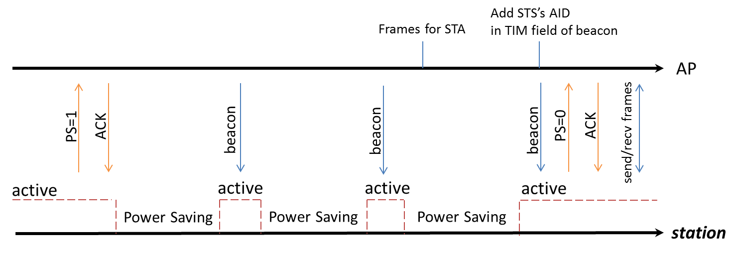
Timeline of power saving
In SDK IEEE 802.11 power management is called LPS, and if NP enters sleep mode when Wi-Fi is in LPS mode, we call it WoWLAN mode.
In WoWLAN mode, a timer with a period of about 102ms will be set in the suspend function. And LP will wake up every 102ms to receive the beacon to maintain the connection.
Except for LPS and WoWLAN, we also have IPS, which can be used when Wi-Fi is not connected. The following tables list all three power-saving modes for Wi-Fi and the relationship between the system power mode and Wi-Fi power mode.
Mode |
Wi-Fi status |
Description |
SDK |
|---|---|---|---|
IPS |
Not associated:
|
Wi-Fi driver automatically turns Wi-Fi off to save power. |
After disabling IPS, the system’s average power consumption will increase significantly. It is not recommended to disable it |
LPS |
Associated:
|
LPS mode is used to implement IEEE 802.11 power management. control RF ON/OFF based on TSF and TIM IE in the beacon. |
LPS mode is enabled in SDK by default but can be disabled through API |
WoWLAN |
Associated: - RF/BB periodically ON/OFF - MAC periodically enters/exits CG/PG |
WiFi will be turned on at each beacon early interrupt to receive a beacon from the associated AP router. Upon receiving a wake-up packet, the system is awakened and the data is passed to the network layer for processing. |
WoWLAN mode is enabled in SDK by default. |
The relationship between system power mode and Wi-Fi power mode is listed in the following table:
System power mode |
Wi-Fi power mode |
Description |
|---|---|---|
Active |
IPS |
Wi-Fi is on, but not connected |
Active |
LPS |
Wi-Fi is connected and enters IEEE 802.11 power management mechanism |
Sleep |
Wi-Fi OFF/IPS |
|
Sleep |
WoWLAN |
Wi-Fi keeps associating. |
Deep-Sleep |
Wi-Fi OFF |
Deep-Sleep is not recommended if Wi-Fi needs to keep on or associated. |
Wakeup Source
The following table lists the wakeup sources that can be used to wake up the system under different power modes.
Wakeup source |
Sleep CG |
Sleep PG |
Deep-Sleep |
Restriction |
|---|---|---|---|---|
WLAN |
√ |
√ |
X |
|
BT |
√ |
√ |
X |
|
IPC |
√ |
√ |
X |
Only KM0 can use the IPC to wake up KM4. |
Basic Timer4~7 |
√ |
√ |
X |
|
PMC Timer |
√ |
√ |
X |
For internal usage |
UART0~2 |
√ |
√ |
X |
|
LOGUART |
√ |
√ |
X |
When using LOGUART as a wakeup source:
|
GPIO |
√ |
√ |
X |
|
I2C |
√ |
√ |
X |
|
CAP_TOUCH |
√ |
√ |
X |
|
ADC |
√ |
√ |
X |
|
SDIO |
√ |
√ |
X |
|
Key-Scan |
√ |
√ |
X |
|
BOR |
√ |
√ |
√ |
|
PWR_DOWN |
√ |
√ |
√ |
|
AON_TIMER |
√ |
√ |
√ |
|
AON_WAKEPIN |
√ |
√ |
√ |
|
RTC |
√ |
√ |
√ |
The following table lists the wakeup sources that can be used to wake up the system under different power modes.
Wakeup source |
Sleep CG |
Sleep PG |
Deep-Sleep |
Restriction |
|---|---|---|---|---|
WLAN |
√ |
√ |
X |
|
BT |
√ |
√ |
X |
|
IWDG |
√ |
√ |
X |
|
IPC |
√ |
√ |
X |
|
Basic Timer |
√ |
√ |
X |
|
UART |
√ |
√ |
X |
|
LOGUART |
√ |
√ |
X |
|
GPIO |
√ |
√ |
X |
|
SPI |
√ |
X |
X |
|
CAP_TOUCH |
√ |
√ |
X |
|
ADC |
√ |
√ |
X |
|
VAD |
√ |
X |
X |
|
BOR |
√ |
√ |
√ |
|
PWR_DOWN |
√ |
√ |
√ |
|
AON_TIMER |
√ |
√ |
√ |
|
AON_WAKEPIN |
√ |
√ |
√ |
|
RTC |
√ |
√ |
√ |
The following table lists the wakeup sources that can be used to wake up the system under different power modes.
Wakeup source |
Sleep CG |
Sleep PG |
Deep-Sleep |
Restriction |
|---|---|---|---|---|
WLAN |
√ |
√ |
X |
|
BT |
√ |
√ |
X |
|
AON_WAKEPIN |
√ |
√ |
√ |
|
UART |
√ |
√ |
X |
|
IPC |
√ |
√ |
X |
The IPC can only wake up CA32 and KM4, but not KM0. |
SPI |
√ |
X |
X |
Do not turn off SOC domain clock and power when using SPI as wakeup source |
USB |
√ |
X |
X |
|
VAD |
√ |
√ |
X |
|
BOR |
√ |
√ |
√ |
|
PWR_DOWN |
√ |
√ |
√ |
|
CAP_TOUCH |
√ |
√ |
X |
|
ADC |
√ |
√ |
X |
|
RTC |
√ |
√ |
√ |
|
GPIO |
√ |
√ |
X |
|
LOGUART |
√ |
√ |
X |
|
Basic Timer |
√ |
√ |
X |
|
IWDG |
√ |
√ |
X |
|
AON_TIMER |
√ |
√ |
√ |
A hardware SYSON power management control module (SYSON PMC) is designed to control the clock and power of LP, and then LP controls the clock and power of NP and AP. When the system enters sleep mode, CPUs can select to enter clock-gating (CG) or power-gating (PG) mode, while SYSON PMC maintained active to wake up LP when wakeup sources are triggered.
The following table lists the wakeup sources that can be used to wake up the system under different power modes.
Wakeup source |
Sleep CG |
Sleep PG |
Deep-Sleep |
Restriction |
|---|---|---|---|---|
WLAN |
√ |
√ |
X |
|
BT |
√ |
√ |
X |
|
IPC |
√ |
√ |
X |
|
Basic Timer |
√ |
√ |
X |
|
UART |
√ |
√ |
X |
When UART0~UART3 are used as wakeup sources:
|
LOGUART |
√ |
√ |
X |
When LOGUART is used as wakeup source:
|
GPIO |
√ |
√ |
X |
|
RMII |
√ |
X |
X |
|
CAP-TOUCH |
√ |
√ |
X |
|
CAN |
√ |
X |
X |
only supporting clock gating, the voltage needs to be maintained at 0.8V, and OSC4M needs to be turned on |
IWDG |
√ |
√ |
X |
|
ADC |
√ |
√ |
X |
|
SDIO |
√ |
X |
X |
Requires PLL to work properly |
USB |
√ |
X |
X |
|
AON_TIMER |
√ |
√ |
√ |
|
AON_WAKEPIN |
√ |
√ |
√ |
|
RTC |
√ |
√ |
√ |
|
BOR |
√ |
√ |
√ |
|
PWR_DOWN |
√ |
√ |
√ |
Entering Sleep Mode
Sleep mode is based on FreeRTOS Tickless, thus it is recommended to enter sleep mode by releasing the wakelock.
Initialize the specific peripheral.
Enable and register the peripheral’s interrupt.
Set
sleep_wevent_config[]inambea_sleepcfg.c, and the interrupt should be registered on the same CPU selected bysleep_wevent_config[].For peripherals that need special clock settings, set
ps_config[]inameba_sleepcfg.cif needed.Register sleep/wakeup callback if needed.
Enter sleep mode by releasing the wakelock in application core (AP) (PMU_OS needs to be released since it is acquired by default when boot).
Clear the peripheral’s interrupt when wakeup.
Entering Deep-Sleep Mode
Deep-Sleep can also be entered from FreeRTOS Tickless flow.
When the system boots, AP holds the deepwakelock PMU_OS,
thus freertos_ready_to_dsleep() will be checked fail and the system does not enter deep-sleep mode in idle task by default.
Since freertos_ready_to_dsleep() will be checked only after freertos_ready_to_sleep() is checked pass,
both the wakelock and deepwakelock need to be released for entering deep-sleep mode.
Configuration:
Initialize the related peripheral and enable its interrupt.
Set
sleep_wakepin_config[]inameba_sleepcfg.cwhen using AON wakepin as a wakeup source.Enter deep-sleep mode by releasing the deepwakelock and wakelock in AP.
Power-Saving Configuration
Please reference User Config chapter for detail information.
UART and LOGUART
For peripherals that require specific clock settings, such as UART and LOGUART, the configuration procedures are described in the following sections.
Initialize UART/LOGUART and enable their interrupts.
Set the wake-up source: In
sleep_wevent_config[], configure the wake-up source (WAKE_SRC_UART0/WAKE_SRC_UART1/WAKE_SRC_UART2_BT/WAKE_SRC_UART_LOG) and specify the CPU to be woken up (WAKEUP_KM4 or WAKEUP_KM0). Ensure the interrupt is registered on the CPU to be woken up.Select the clock source:
XTAL: In
ps_config[], set xtal_mode_in_sleep to XTAL_Normal and set keep_OSC4M_on to TRUE.OSC2M: In
ps_config[], set keep_OSC4M_on to TRUE.
Set the operating voltage: In
ps_config[], setsleep_to_08Vto TRUE.Enter sleep mode by releasing the wake lock on KM4 (PMU_OS needs to be released because it is acquired by default at system startup).
Clear the UART/LOGUART interrupt after waking up.
Note
When using UART as a wake-up source, the following limitations apply:
The Rx clock source can only be OSC2M, and OSC4M must not be turned off during sleep. It is not recommended to use UART as a wake-up source when the baud rate is greater than 115200.
Before sleep, you need to call the API
RCC_PeriphClockSource_UART(UARTx_DEV, UART_RX_CLK_OSC_LP)to switch the clock to OSC2M.If higher baud rate is required after waking up, you can use the API
RCC_PeriphClockSource_UART(UARTx_DEV, UART_RX_CLK_XTAL_40M)to switch to XTAL40M Rx clock.
Any part of commands used for wake-up that exceed the FIFO depth (64 bytes) will be lost.
When using LOGUART as a wake-up source, the following limitations apply:
If the Rx clock source is OSC2M, OSC4M must not be turned off during sleep.
Before sleep, you need to call the API
RCC_PeriphClockSource_LOGUART(LOGUART_CLK_OSC_LP)to switch the clock to OSC2M.If higher baud rate is required after waking up, you can use the API
RCC_PeriphClockSource_LOGUART(LOGUART_CLK_XTAL_40M)to switch to XTAL40M Rx clock.
If the Rx clock source is XTAL40M, XTAL must not be turned off during sleep.
Any part of commands used for wake-up that exceed the FIFO depth (16 bytes) will be lost.
For peripherals that require specific clock settings, such as UART and LOGUART, the configuration procedures are described in the following sections.
Initialize UART/LOGUART and enable their interrupts.
Set the wake-up source: In
sleep_wevent_config[], set the wake-up source (WAKE_SRC_UART0/WAKE_SRC_UART1/WAKE_SRC_UART2/WAKE_SRC_UART3/WAKE_SRC_UART_LOG) and specify the CPU to be woken up (WAKEUP_AP or WAKEUP_NP). Ensure the interrupt is registered on the CPU to be woken up.Set the clock source: In
ps_config[], set xtal_mode_in_sleep to XTAL_Normal.Enter sleep mode by releasing the wake lock on KM4 (PMU_OS needs to be released because it is acquired by default at system startup).
Clear the UART/LOGUART interrupt upon waking up.
Note
When using UART as a wake-up source, the following limitations exist:
When the Rx clock source is XTAL40M, do not turn off XTAL during sleep.
Any part of a wake-up command exceeding the FIFO depth (64 bytes) will be lost.
When using LOGUART as a wake-up source, the following limitations exist:
When the Rx clock source is XTAL40M, do not turn off XTAL during sleep.
Any part of a wake-up command exceeding the FIFO depth (16 bytes) will be lost.
For peripherals that require specific clock settings, such as UART and LOGUART, the configuration procedures are described in the following sections.
UART
Initialize UART/LOGUART and enable their interrupts.
Set the wake-up source: In
sleep_wevent_config[], set the relevant wake-up source (WAKE_SRC_UART0/WAKE_SRC_UART1/WAKE_SRC_UART2/WAKE_SRC_UART_LOG) and specify the CPU to be woken up (WAKEUP_AP/WAKEUP_NP/WAKEUP_LP). Ensure the interrupt is registered on the corresponding CPU.Select the clock source:
XTAL: In
ps_config[], set xtal_mode_in_sleep to XTAL_Normal and set keep_OSC4M_on to TRUE.OSC2M: In
ps_config[], set keep_OSC4M_on to TRUE.
Enter sleep mode by releasing the wake lock on KM4 (PMU_OS needs to be released because it is acquired by default at system startup).
Clear the UART/LOGUART interrupt upon wake-up.
Note
When using UART as a wake-up source, the following limitations apply:
If the Rx clock source is XTAL40M, do not turn off XTAL during sleep.
If the Rx clock source is OSC2M, do not turn off OSC4M during sleep.
Before sleep, call the API
RCC_PeriphClockSource_UART(UARTx_DEV, UART_RX_CLK_OSC_LP)to switch the clock to OSC2M.If a higher baud rate is needed after waking up, call
RCC_PeriphClockSource_UART(UARTx_DEV, UART_RX_CLK_XTAL_40M)to switch to XTAL40M Rx clock.
Any part of a wake-up command exceeding the FIFO depth (64 bytes) will be lost.
When using LOGUART as a wake-up source, the following limitations apply:
If the Rx clock source is XTAL40M, do not turn off XTAL during sleep.
If the Rx clock source is OSC2M, do not turn off OSC4M during sleep.
Before sleep, call the API
RCC_PeriphClockSource_LOGUART(UARTLOG_CLK_OSC_LP)to switch the clock to OSC2M.If a higher baud rate is needed after waking up, call
RCC_PeriphClockSource_LOGUART(UARTLOG_CLK_XTAL_40M)to switch to XTAL40M Rx clock.
Any part of a wake-up command exceeding the FIFO depth (16 bytes) will be lost.
For peripherals that require specific clock settings, such as UART and LOGUART, the configuration procedures are described in the following sections.
Initialize UART/LOGUART and enable their interrupts.
Set the wake-up source: In
sleep_wevent_config[], configure the wake-up source (WAKE_SRC_UART0/WAKE_SRC_UART1/WAKE_SRC_UART2/WAKE_SRC_UART3/WAKE_SRC_UART_LOG) and specify the CPU to be woken up (WAKEUP_AP or WAKEUP_NP). Ensure the interrupt is registered on the CPU to be woken up.Select the clock source:
OSC2M/OSC4M: In
ps_config[], set keep_osc4m_on_in_sleep to TRUE.XTAL: In
ps_config[], set xtal_mode_in_sleep to XTAL_Normal and keep_osc4m_on_in_sleep to TRUE.
Set the operating voltage: In
ps_config[], setregu_state_in_sleepto STATE2_LDOPC_SWRPFM_08.Enter sleep mode by releasing the wake lock on AP (PMU_OS needs to be released because it is acquired by default at system startup).
Clear the UART/LOGUART interrupt after waking up.
Note
When using UART as a wake-up source, the following limitations apply:
If the Rx clock source is OSC2M, OSC4M must not be turned off during sleep. It is not recommended to use this clock source when the baud rate is greater than 115200.
Before sleep, switch the clock to OSC2M via API
RCC_PeriphClockSourceSet(UARTx, OSC2M).After waking up, if a higher baud rate is required, switch to XTAL40M Rx clock via API
RCC_PeriphClockSourceSet(UARTx, XTAL).
If the Rx clock source is XTAL40M, both XTAL40M and OSC4M must not be turned off during sleep.
Any part of commands used for wake-up that exceed the FIFO depth (64 bytes) will be lost.
When using LOGUART as a wake-up source, the following limitations apply:
If the Rx clock source is OSC2M, OSC4M must not be turned off during sleep.
Before sleep, switch the clock to OSC4M via API
RCC_PeriphClockSourceSet(LOGUART, OSC4M).After waking up, if a higher baud rate is required, switch to XTAL40M Rx clock via API
RCC_PeriphClockSourceSet(LOGUART, XTAL).
If the Rx clock source is XTAL40M, XTAL must not be turned off during sleep.
Any part of commands used for wake-up that exceed the FIFO depth (16 bytes) will be lost.