Flash Program Tool
Resources
Introduction
The Image Tool is the official image download tool developed by Realtek for Ameba series SoC.
Flash Type |
UART |
USB |
|---|---|---|
NOR Flash |
Support |
Support |
Flash Type |
UART |
USB |
|---|---|---|
NOR Flash |
Support |
Not support |
Flash Type |
UART |
USB |
|---|---|---|
NOR Flash |
Support |
Not support |
Flash Type |
UART |
USB |
|---|---|---|
NOR Flash |
Support |
Not support |
Flash Type |
UART |
USB |
|---|---|---|
NOR Flash |
Support |
Support |
NAND Flash |
Support |
Support |
Flash Type |
UART |
USB |
|---|---|---|
NOR Flash |
Support |
Support |
The UI of the Image Tool is shown below.
Hardware Setup
The hardware setup for image download is shown below.


Note
USB <—> LOGUART: The LOGUART port can be used for console viewing of device logs and for firmware flashing
USB <—> USB: The USB port can be used for firmware flashing
Customers can flexibly choose ports according to the actual configuration of the device.
Software Setup
Environment Requirements: EX. WinXP, Win 7 or later, Microsoft .NET Framework 4.0.
Software location:
Image Tool:
{SDK}/tools/ameba/ImageTool/AmebaImageTool.exeDevice Profile Editor:
{SDK}/tools/ameba/DeviceProfileEditor/AmebaDeviceProfileEditor.exe
Device profiles:
{SDK}/tools/ameba/DeviceProfilesDevice profiles provide the necessary device information required for image download, with the naming rules:
<SoC name>_<OS type>_<Flash type>[_<Extra info>].rdev
Where:
- SoC name:
the name of Realtek Ameba SoC
- OS type:
FreeRTOS or Linux
- Flash type:
NOR or NAND
- Extra info:
extra information like Flash size, application, etc.
Note
{ImageTool}will refer to{SDK}/tools/ameba/ImageToolin the subsequent sections.To download firmware via the LOGUART interface, it is necessary to install the main controller driver for the onboard USB-to-UART adapter (such as PL2303GC). Please check the official website of the respective USB-to-UART adapter manufacturer for specific drivers.
For Windows XP or Windows 7, if you need to download firmware via the USB interface, you must first install the USB driver
ImageTool/RtkUsbCdcAcmSetup.INF.
Image Files
Image Name |
Description |
Mandatory? |
|---|---|---|
km4_boot_all.bin |
KM4 bootloader |
Yes |
km0_km4_app.bin |
KM0/KM4 applications |
Yes |
km0_km4_app_mp.bin |
KM0/KM4 MP applications |
No |
Image name |
Description |
Mandatory? |
|---|---|---|
km4_boot_all.bin |
KM4 bootloader |
Yes |
kr4_km4_app.bin |
KR4/KM4 applications |
Yes |
kr4_km4_app_mp.bin |
KR4/KM4 MP applications |
No |
Image name |
Description |
Mandatory? |
|---|---|---|
km4_boot_all.bin |
KM4 bootloader |
Yes |
kr4_km4_app.bin |
KR4/KM4 applications |
Yes |
kr4_km4_app_mp.bin |
KR4/KM4 MP applications |
No |
For DSP-related matters, please refer to DSP Build 。
Image name |
Description |
Mandatory? |
|---|---|---|
km4_boot_all.bin |
KM4 bootloader |
Yes |
kr4_km4_app.bin |
KR4/KM4 applications |
Yes |
kr4_km4_app_mp.bin |
KR4/KM4 MP applications |
No |
For DSP-related matters, please refer to DSP Build 。
Image name |
Description |
Mandatory? |
|---|---|---|
km4_boot_all.bin |
KM4 bootloader |
Yes |
km0_km4_ca32_app.bin |
KM0/KM4/CA32 applications |
Yes |
Image name |
Description |
Mandatory? |
|---|---|---|
A: km4_boot_all.bin |
A slot: KM4 bootloader |
Yes |
A: km0_km4_app.bin |
A slot: KM0/KM4 applications |
Yes |
A: boot.img |
A slot: CA32 firmware package, including BL1, BL2, BL32 and BL33 |
Yes |
B: km4_boot_all.bin |
B slot: KM4 bootloader |
No |
B: km0_km4_app.bin |
B slot: KM0/KM4 applications |
No |
B: boot.img |
B slot: CA32 firmware package, including BL1, BL2, BL32 and BL33 |
No |
A: vbmeta.img |
A slot: AP Linux meta data image, only for secure boot |
No |
B: vbmeta.img |
B slot: AP Linux meta data image, only for secure boot |
No |
A: xxx.dtb* |
A slot: AP Linux DTB (device tree blob) |
Yes |
B: xxx.dtb* |
B slot: AP Linux DTB for recovery |
No |
A: kernel.img |
A slot: AP Linux kernel |
Yes |
B: kernel.img |
B slot: AP Linux kernel |
No |
rootfs.img |
AP Linux rootfs binary |
Yes |
userdata.img |
AP user data binary |
Yes |
Note
* : A suitable .dtb file needs to be selected based on actual usage.
Image Name |
Description |
Mandatory? |
|---|---|---|
km4_boot_all.bin |
KM4 bootloader |
Yes |
km0_km4_app.bin |
KM0/KM4 applications |
Yes |
km0_km4_app_mp.bin |
KM0/KM4 MP applications |
No |
Note
For specific Flash partition information, please refer to Flash Layout 。
Download Steps
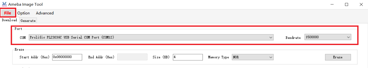
Basic Configuration
Select the Device Profile.
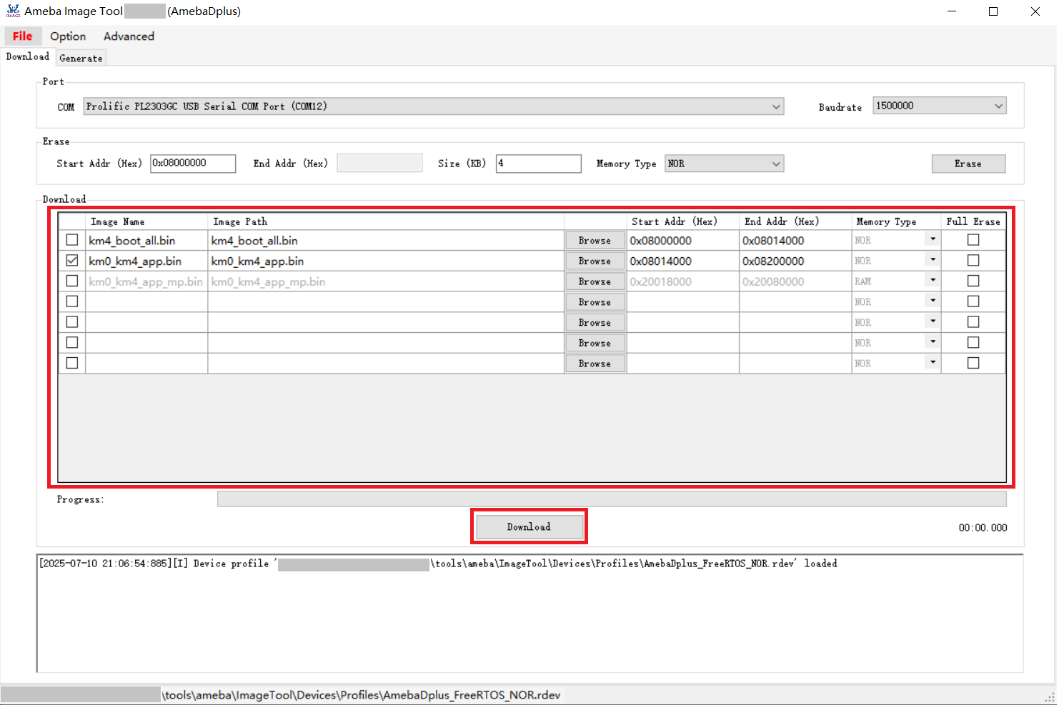
Open Image Tool, click and select the device profile
AmebaDplus_FreeRTOS_NOR.rdev.Open Image Tool, click and select the device profile
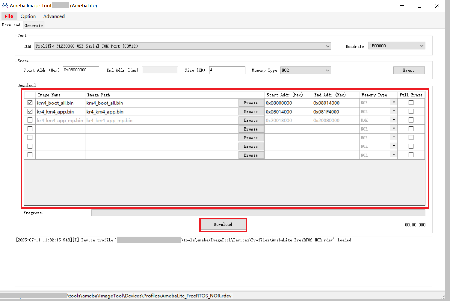
AmebaLite_FreeRTOS_NOR.rdev.Open Image Tool, click and select the device profile
AmebaLite_FreeRTOS_NOR.rdev.Open Image Tool, click and select the device profile
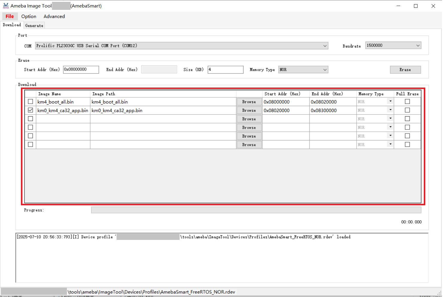
AmebaLite_FreeRTOS_NOR.rdev.Open the Image Tool, click and select the proper device profile.
For NOR Flash SoC, select
AmebaSmart_FreeRTOS_NOR.rdev.For NAND Flash SoC, select
AmebaSmart_FreeRTOS_NAND.rdev.
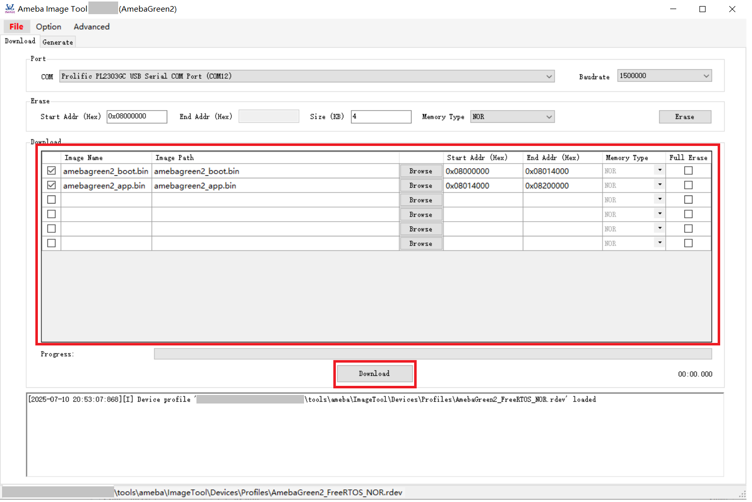
Open Image Tool, click and select the device profile
AmebaGreen2_FreeRTOS_NOR.rdev.Note
After the Device Profile is loaded, it will be saved in the
{ImageTool}/setting.jsonfile. Each time you restart the programming tool, it will be loaded by default, without the need for repeated setup.Select the appropriate serial port and set the transmission baud rate. The default baud rate is 1500000.
Note
After the baud rate is set, it will be saved in the
{ImageTool}/setting.jsonfile. Each time you restart the programming tool, it will be loaded by default, eliminating the need for repeated configuration. For USB downloads, the baud rate can be disregarded.
Enter Download Mode
Depending on the current state of the device, the way to enter download (flashing) mode differs. In principle, there are two approaches:
Software-initiated (including ROM‐level support)
The application/ROM already contains the command reboot uartburn. When the system receives this command over the UART, it will switch to download mode—even on a blank chip.Therefore, if the device’s UART can respond to the reboot uartburn command, no extra operation is required: the flashing tool will send the command, the device automatically enters download mode, and firmware download starts immediately.
Hardware-triggered by an electrical signal
Tie the
LOGUART Txpin to GND, then reboot the device, and finally release (disconnect) theLOGUART Txpin from GND. If the software method does not work, you can force the device into download mode in this way. For the location and description of theLOGUART Txpin, see section :ref:trap_pins.Realtek Module
Press UART_DOWNLOAD down and keep it pressed.
Press CHIP_EN button.
Release the UART_DOWNLOAD button.
Customer-specific board (no buttons available)
Short the
LOGUART Txpin to GND.Power-cycle the device.
Remove the short between
LOGUART Txand GND.
Automatic entry via external DTR/RTS control
Customer can also use external DTR/RTS signals to control the
LOGUART TxandCHIP_ENpins so that the device enters download mode automatically. The Realtek EVB includes a reference circuit for this DTR/RTS-controlled auto-download function. The circuit is disabled by default but can be enabled through a specific procedure (see Automatic flashing solution ). Once enabled, the board will switch to download mode automatically; you only need to set the corresponding parameters in the flashing tool (detailed in DTR/RTS Configuration ).Customers may design their own circuit and timing scheme for automatic download mode, according to their specific requirements.
The device is now in Download Mode and ready for the next operation.
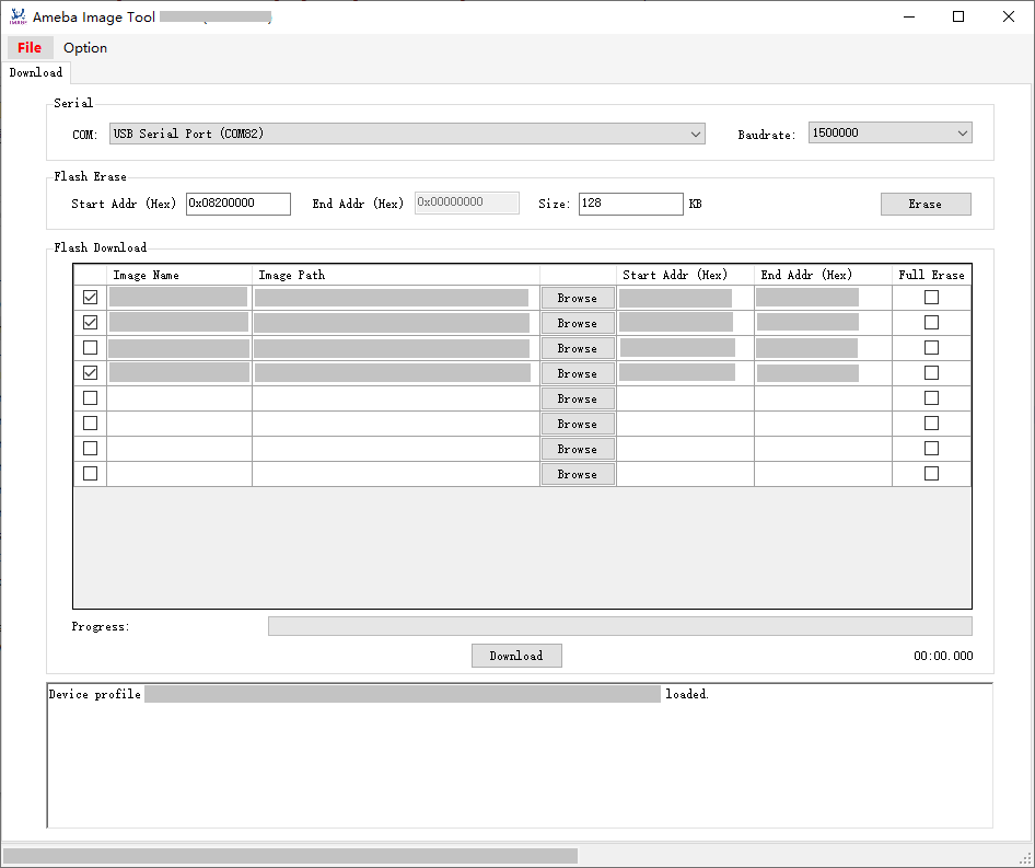
The image download steps are illustrated below:
Refer to Basic Configuration
Click the button to select the image for download.
Note
Flash layout modifications are permissible via the Image Tool if absolutely necessary. It is recommended to use the
Device Profile Editorinstead of theImage Toolto modify the Flash layout, and ensure the Flash layout in the SDK is updated accordingly. For more details, refer to the section Modifying Device Profile .Click the button to initiate the process.
The progress bar will display the current download progress of the image, and the log window will show the operation status.
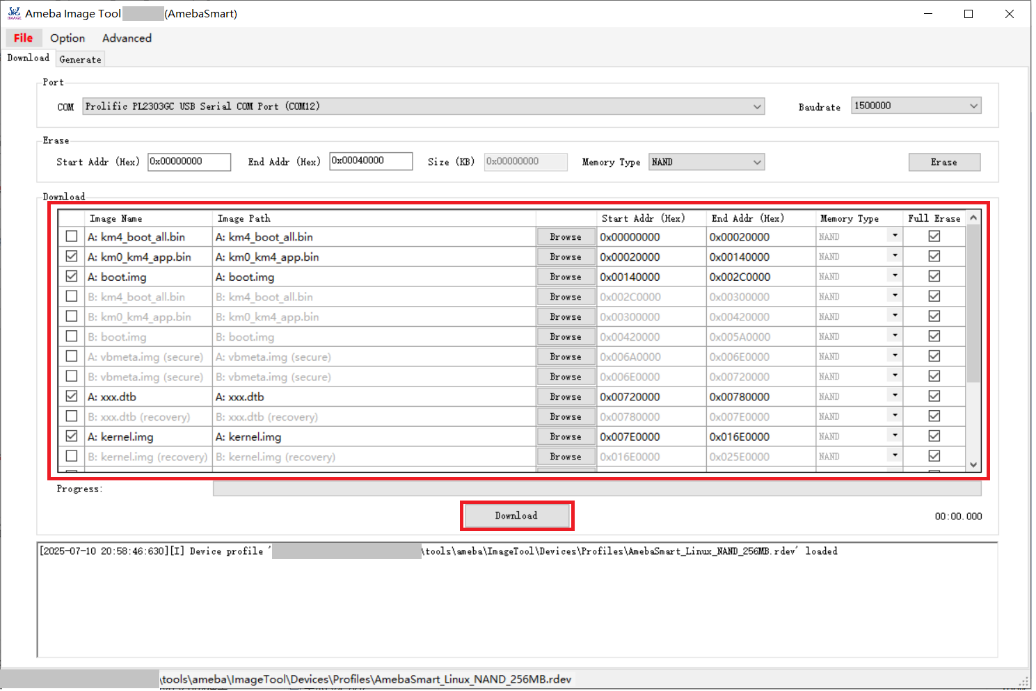
Image download operation
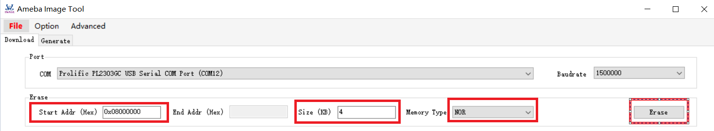
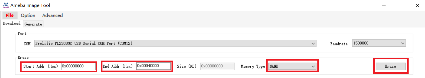
Flash Erase
Steps to erase Flash are illustrated below:
Refer to Basic Configuration .
Select the appropriate .
Enter the erase start address.
For NOR Flash, the value should be aligned to 4KB.
For NAND Flash, the value should align with the block size.
Note
Please refer to the datasheet of the respective NAND Flash for block size details.
Enter the erase size or the erase cut-off address.
For NOR Flash, the erase size must be a multiple of 4KB.
For NAND Flash, the erase cut-off address should be a multiple of the block size (exclusive of the cut-off address).
Note
Please refer to the respective NAND Flash datasheet to obtain the block size.
Click the button to start the erase operation.
The operation result can be obtained from the log window.
Note
Manual erasure of Flash is not required before image download, as Flash will be automatically erased during the image download process.
If Flash block protection is detected at Step 5, please refer to the Flash Block Protection Process section for detailed information.
Flash Register Access
This feature is intended for professional use only to access Flash status registers. It has been supported since version v2.2.0.
Caution
Operations involving Flash registers, particularly write operations, must adhere to the Flash datasheet guidelines to prevent potential Flash data loss or even damage.
The common pre-steps for accessing Flash registers are as follows:
Ensure the Image Tool is closed.
Edit the
<ImageTool>/Setting.jsonfile and set the value of ExpertMode to a non-zero integer (e.g., 1) to enter expert mode.Refer to Basic Configuration .
Specific operations for NOR or NAND register access are detailed below:
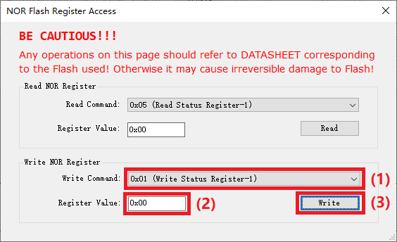
In addition to common pre-steps, click and select to open the NOR Flash Register Access dialog:
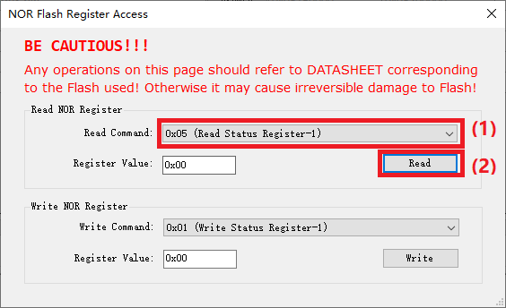
After completing the common pre-steps, follow these steps to read NOR Flash registers:
Select to access specific registers.
Click the button; the register value will be displayed in the register value text box.
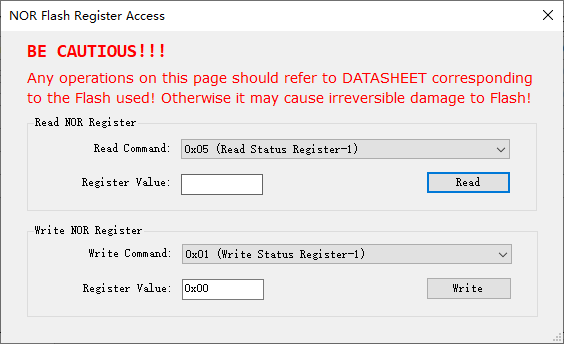
After completing the common pre-steps, follow these steps to write to NOR Flash registers:
Select to target specific registers.
Input the register value.
Click the button to commit the register value.
You may read back the register value for verification.
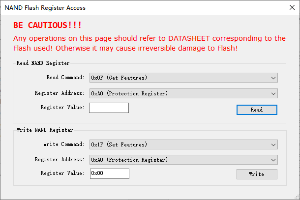
In addition to common pre-steps, click and choose to open the NAND Flash Register Access dialog:
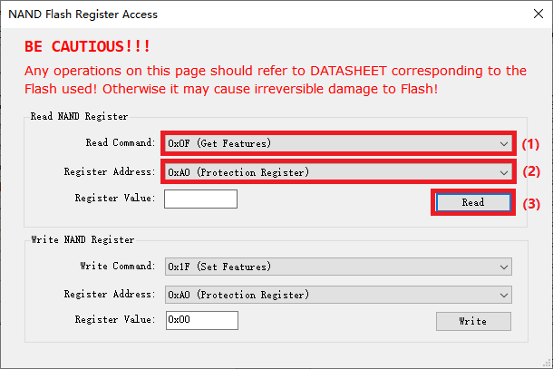
After completing the common pre-steps, follow these steps to read NAND Flash registers:
Select to access specific registers.
Choose .
Click the button; the register value will be displayed in the register value text box.
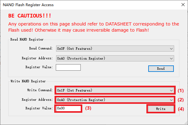
After completing the common pre-steps, follow these steps to read NAND Flash registers:
Select to target specific registers.
Choose .
Enter .
Click the button to commit the register value.
You can read back the register value for verification.
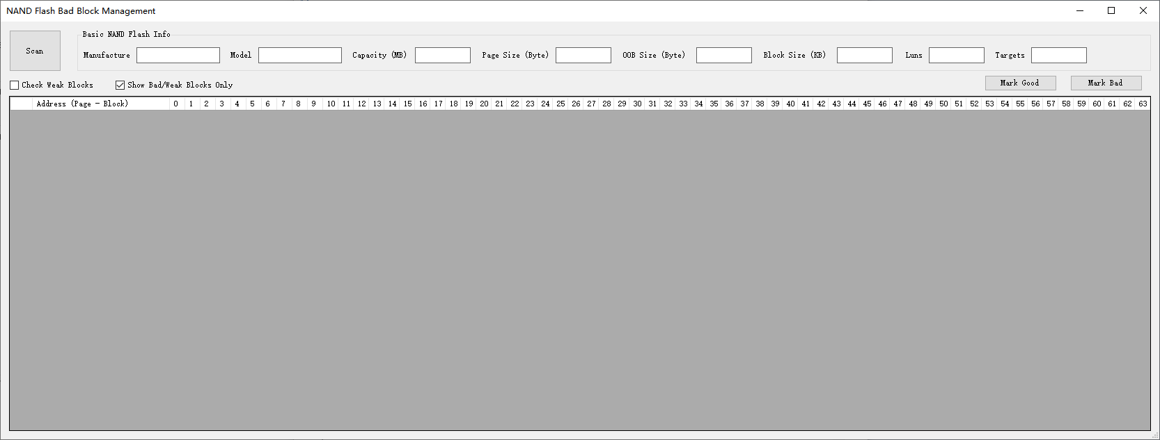
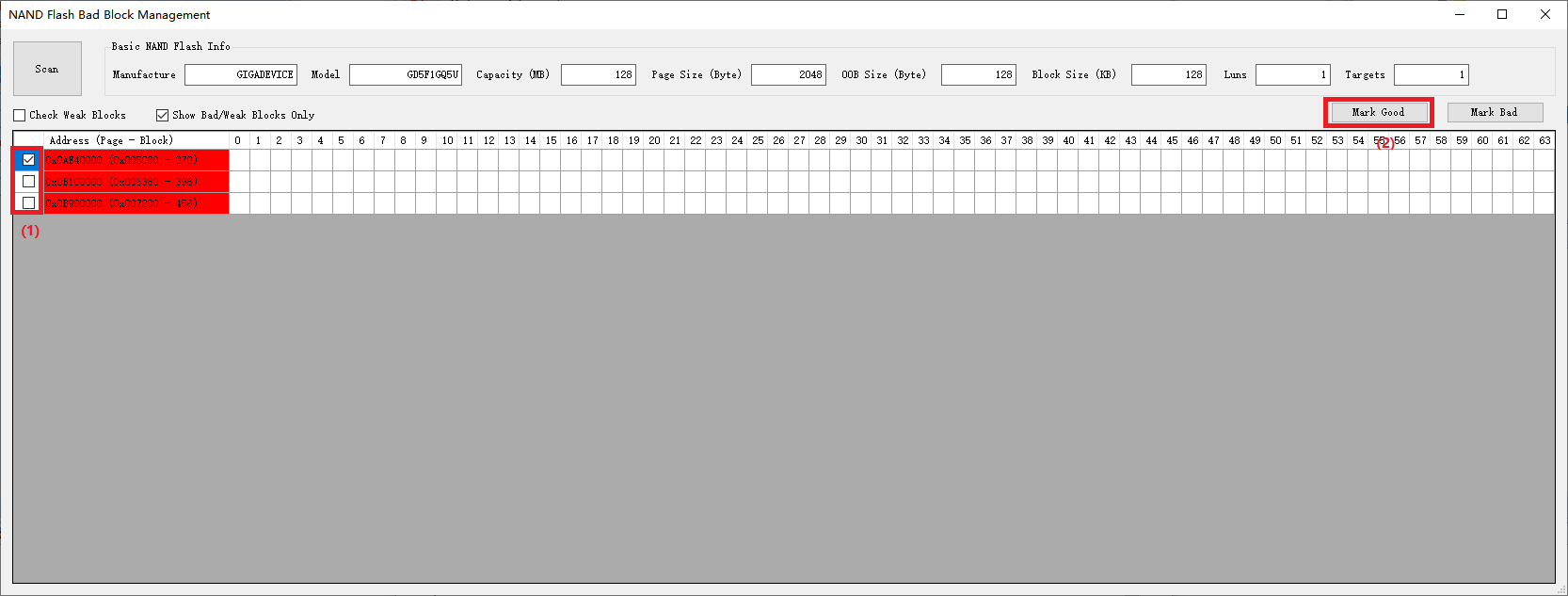
NAND Bad Block Management
This feature is intended for professional use only to scan or mark the status of NAND blocks. It has been supported since version v2.5.10.
Common pre-steps for NAND bad block management:
Ensure the Image Tool is closed.
Edit the
<ImageTool>/Setting.jsonfile and set the value of ExpertMode to a non-zero integer (e.g., 1) to enter expert mode.Refer to Basic Configuration .
Click and select to open the NAND Flash Bad Block Management dialog:
Scan Block Status
After completing the common pre-steps, proceed with the following steps to scan block status:
(Optional) Select the :menuselection:Check Weak Blocks checkbox if required.
By default, if unchecked, the Image Tool will only scan the bad markers of each block to produce a list of bad blocks.
If checked, the Image Tool will perform a comprehensive scan of all block statuses and the statuses of all pages within non-bad blocks, providing a detailed status report of blocks and pages. Note that this operation requires significantly more time than a bad-block-only scan.
(Optional) Select the :menuselection:Show Bad/Weak Blocks Only checkbox if preferred.
By default, if unchecked, the Image Tool will display the status of all blocks.
If checked, the Image Tool will only display the status of bad and weak blocks.
It is recommended to enable this option for clearer results.
Click the button.
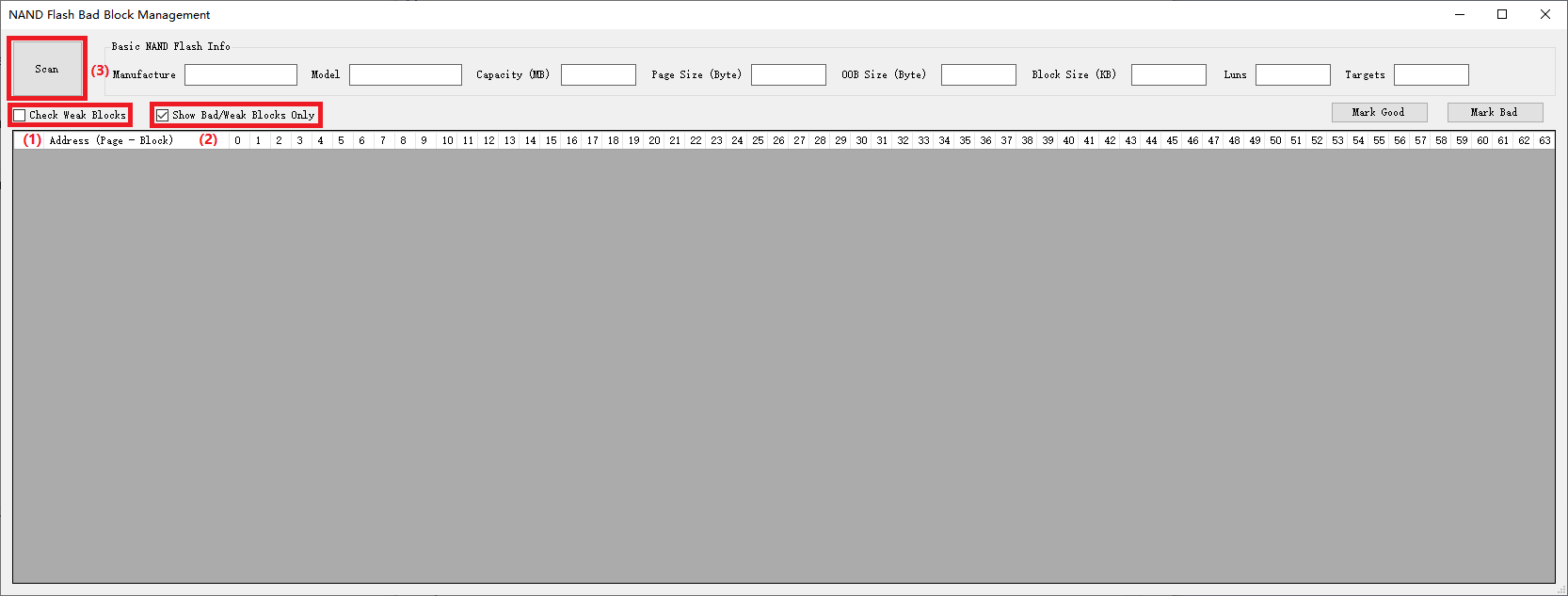
Scanning operation for NAND Flash block status
The scan results will be displayed as follows:
For a bad-block-only scan, bad blocks will be indicated with a red background color in the Address cell.
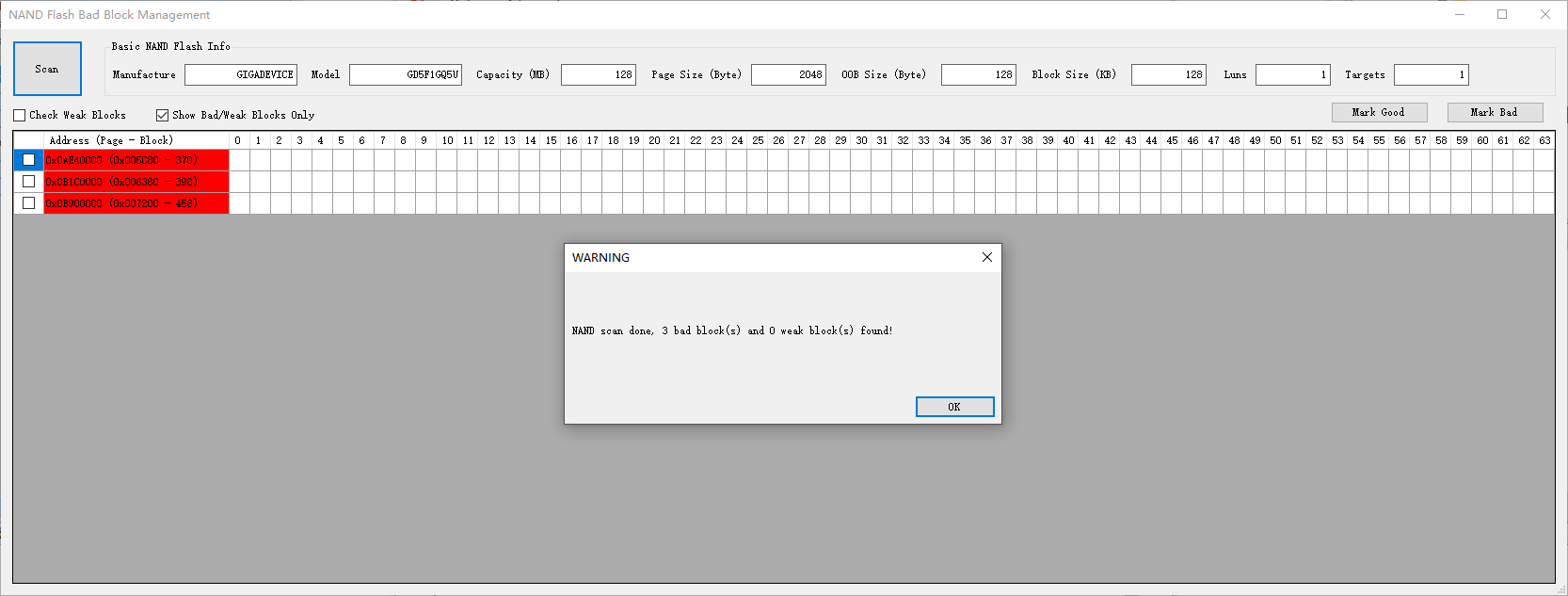
Results of NAND Flash bad block scan
For a detailed weak block scan, both the block Address cells and page cells will be color-coded:
Bad blocks have their Address cells marked in red, while pages remain unmarked.
Weak blocks have their Address cells marked as follows:
Yellow: Indicates only bit flip warnings for all pages within the block.
Orange: Indicates any bit flip errors across all pages within the block.
Brown: Indicates any fatal bit flip errors across all pages within the block.
Gray: Indicates any other errors detected during status scans on any pages within the block.
Weak pages have their cells marked as follows:
Yellow: The page read resulted in a bit flip warning.
Orange: The page read resulted in a bit flip error.
Brown: The page read resulted in a fatal bit flip error.
Gray: The page read resulted in any other errors.
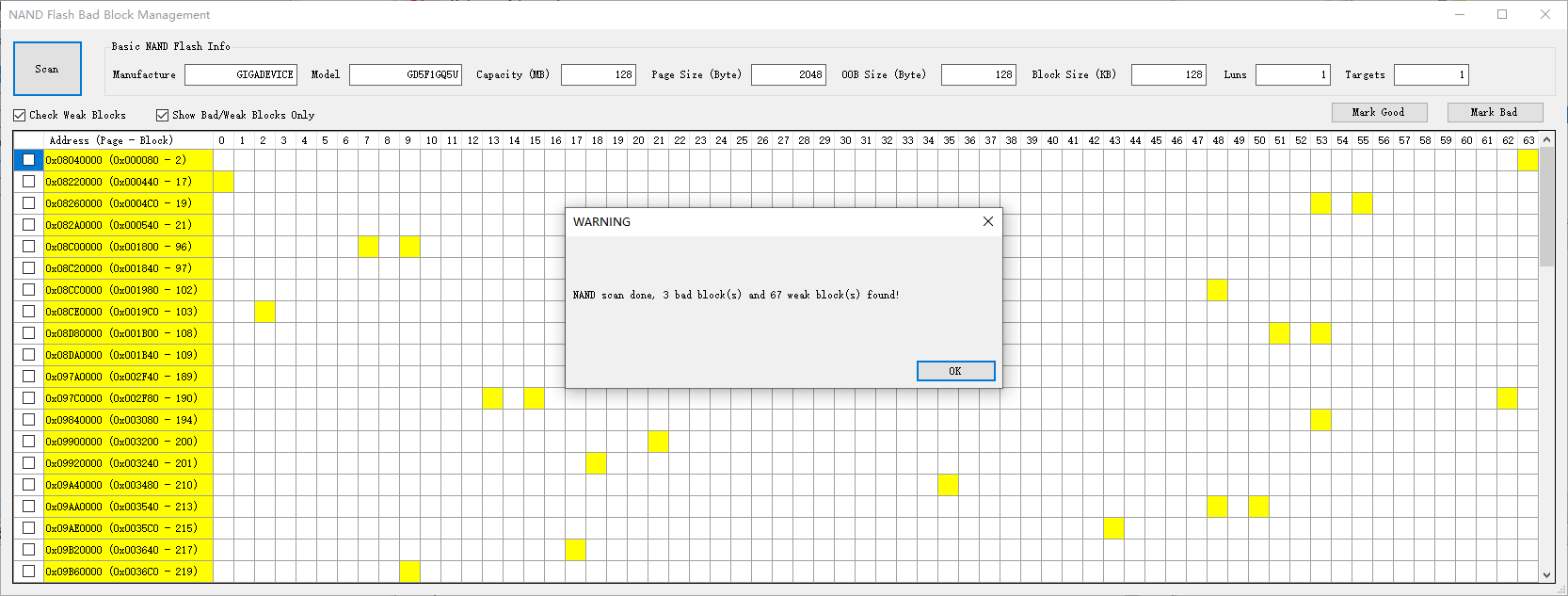
Results of NAND Flash weak block scan
Mark Block Status
After performing block scanning operations, users can mark the status of specified blocks as good or bad. This feature is intended exclusively for internal debugging purposes.
Caution
Exercise caution when modifying block status, especially when marking a bad block as good.
To mark non-bad blocks as bad:
Select one or more non-bad blocks.
Click the button and confirm the operation.

To mark bad blocks as good:
Select one or more bad blocks.
Click the button and confirm the operation.
Flash Block Protection Detection
During image download or flash erase operations, if a flash block protection configuration is detected on the device, the Image Tool will prompt a dialog to guide the user through subsequent actions.
For NOR Flash, only the Flash type and protection register value will be displayed.
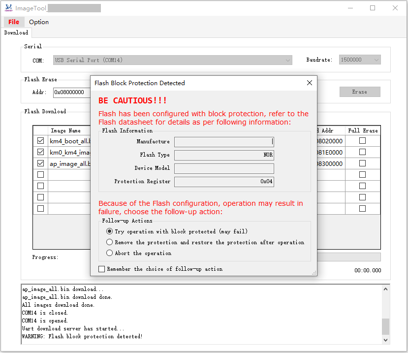
For NAND Flash, detailed Flash information will be presented.
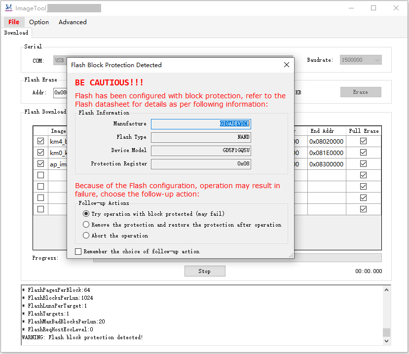
The system provides users with the following options for subsequent actions:
Attempt the operation with the block protected (operation may fail)
Remove protection, and restore it after the operation
Abort the operation
Additionally, users can check the checkbox to save their choice for future operations and can uncheck to clear the remembered choice.
Modify Device Profile
The procedure for modifying an existing Device Profile encompasses the following steps:
Initiate the Device Profile Editor.
Click the Open button to load an existing device profile.
Change the
Flash Layoutconfiguration as necessary.Image Name: The name of the image compiled by the SDK.Start Address: The initial address in hexadecimal format. For NAND Flash, this value should be aligned with the block size.End Address: The terminal address in hexadecimal format. For NAND Flash, this value should align with the block size, and the partition size must be a multiple of the block size. A suitable proportion of spare blocks (at least one) should be allocated for bad block management.Full Erase: Indicates whether ImageTool should erase the entire partition before downloading the image.Checked: Full erase, typically used for file system partitions; all partitions for NAND Flash are checked by default and cannot be unchecked.
Unchecked: Partial erase, erasing only the actual size of the image file, applicable only to non-file-system partitions of NOR Flash.
Mandatory: Indicates whether ImageTool enables the partition for downloading by default.Checked: Mandatory partition, enabled by default.
Unchecked: Optional partition, disabled by default.
Description: A text description of the image that displays information when hovering the mouse over the image.
Click the Save button to overwrite the existing device profile or click Save As button to save the modified device profile to a new file.
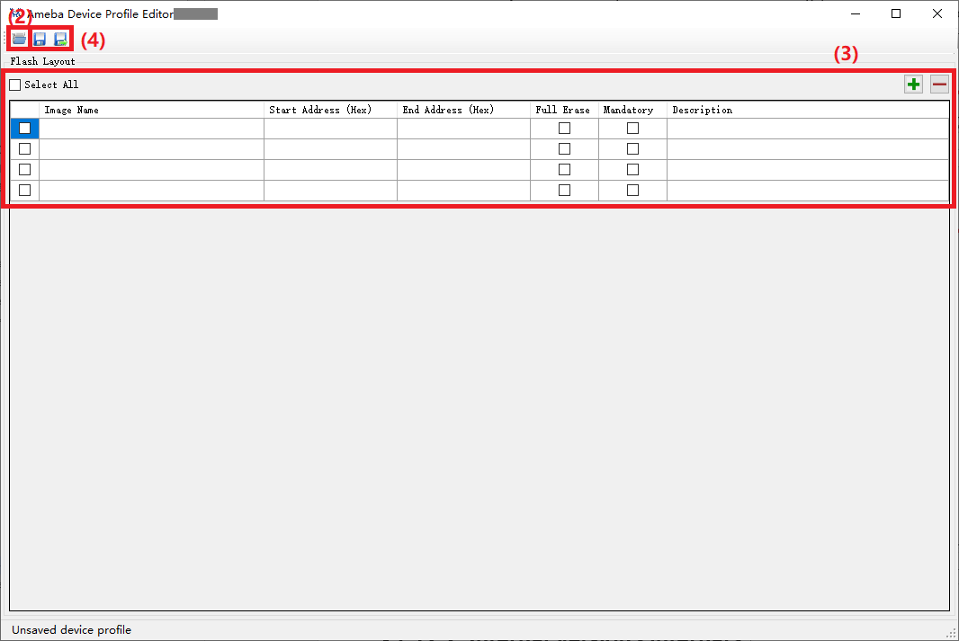
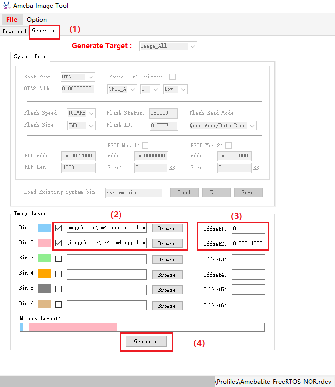
Image Composition
This function enables the amalgamation of multiple image files into a single image file based on specified offsets. This feature has been supported since version v2.7.10.
The procedure for image composition is as follows:
Click to access the image composition page.
Click to sequentially select the image files to be composed, ensuring each is checked.
Enter the corresponding offset for each image file in the field.
Click the button to initiate the composition process.
In the pop-up window, select the save path for the composed image, edit the file name, and click the button to complete the composition.