Flash Program Tool(1toN)
Resources
Introduction
The Ameba 1-N MP ImageTool is a firmware download tool developed by Realtek specifically for the Ameba series of system-on-chip (SoC). This tool is designed to provide an efficient and reliable firmware flashing solution, supporting the simultaneous programming of multiple Ameba devices.
Hardware Setup
The hardware setup for firmware downloading is shown below.


Software Setup
Environment requirements: EX. Winows XP, Winows 7 higher, Microsoft .NET Framework 4.0
Software location:
Ameba_1-N_MP_ImageTool.exe:
{SDK}/tools/ameba/MP_ImageTool_1_N/Ameba_1-N_MP_ImageTool.exeDevice Profiles:
{SDK}/tools/ameba/ImageTool/Devices/Profiles
Note
{MP ImageTool}will be used for short of{SDK}/tools/ameba/MP_ImageTool_1_N/Ameba_1-N_MP_ImageTool.exein the following sections.To download images through UART interface, the host driver for USB to UART adapter (e.g. PL2303GC) on the board shall be installed first, please find the exact driver from the official website of corresponding vendor of the USB to UART adapter.
Do not modify or delete
floader_amebaxxx.binfiles, because they are flashloader binary files.For WinXP or Win7 only, install the USB driver
SDK/tools/ameba/MP_ImageTool_1_N/RtkUsbCdcAcmSetup.INFif there is a need to download images through USB interface.
Image Download
Depending on the current state of the device, the way to enter download (flashing) mode differs. In principle, there are two approaches:
Software-initiated (including ROM‐level support)
The application/ROM already contains the command reboot uartburn. When the system receives this command over the UART, it will switch to download mode—even on a blank chip.Therefore, if the device’s UART can respond to the reboot uartburn command, no extra operation is required: the flashing tool will send the command, the device automatically enters download mode, and firmware download starts immediately.
Hardware-triggered by an electrical signal
Tie the
LOGUART Txpin to GND, then reboot the device, and finally release (disconnect) theLOGUART Txpin from GND. If the software method does not work, you can force the device into download mode in this way. For the location and description of theLOGUART Txpin, see section :ref:trap_pins.
Realtek Module
Press UART_DOWNLOAD down and keep it pressed.
Press CHIP_EN button.
Release the UART_DOWNLOAD button.
Customer-specific board (no buttons available)
Short the
LOGUART Txpin to GND.Power-cycle the device.
Remove the short between
LOGUART Txand GND.Automatic entry via external DTR/RTS control
Customer can also use external DTR/RTS signals to control the
LOGUART TxandCHIP_ENpins so that the device enters download mode automatically. The Realtek EVB includes a reference circuit for this DTR/RTS-controlled auto-download function. The circuit is disabled by default but can be enabled through a specific procedure (see Automatic flashing solution ). Once enabled, the board will switch to download mode automatically; you only need to set the corresponding parameters in the flashing tool (detailed in DTR/RTS Configuration ).Customers may design their own circuit and timing scheme for automatic download mode, according to their specific requirements.
After confirming the status of the device, you can begin downloading the firmware.
The Ameba 1-N MP ImageTool offers Graphical User Interface (GUI) mode and Command-Line Interface (CLI) mode for firmware downloading. Below is a detailed introduction to both modes:
GUI Mode
Download Flow
The steps to download images in normal mode are as follows:
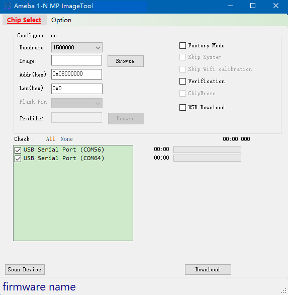
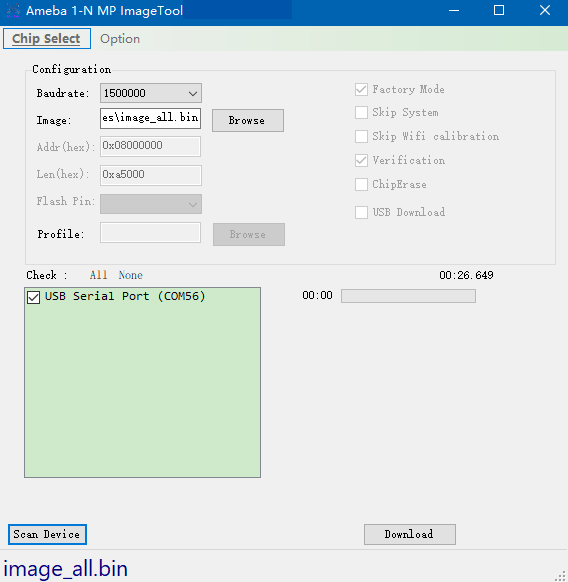
Double click
Ameba_1-N_MP_ImageTool.exe.Click to select DUT type.
Note
Once the chip is selected, some button/checkbox is gray and unable to be accessed, it means that the function is not supported for the selected IC.
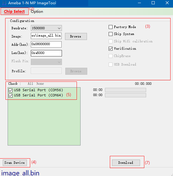
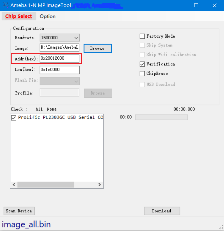
Set the Configuration
- Baudrate:
Select the baudrate for image download, default value is 1500000.
- Image:
Click Browse button to choose the target image file.
- Addr(hex):
Input the destination address to download.
- Leg(hex):
Input image length to download, and it will fill when selected target image file.
And other Optional Functions settings.
Click Scan Device button, the detected devices are listed in the box.
If USB Download is selected, the devices detected and shown in the box are
USB COMs.If USB Download is not selected, the devices detected and shown in the box are
LOGUART COMs.
Note
If some devices are not present immediately, check if the driver is still installing and wait until the installation is finished. This situation is usually encountered when DUT is plugged into PC the first time.
Tick in the checkbox to select the target devices.
Get the DUTs into UART_DOWNLOAD mode.
Click Download button.
Ameba 1-N MP ImageTool operation
Once click Download button, image download starts.
If the image download is in process, as the following figures show, a light bulb shows up at the end of each progress bar, and a stopwatch measures the elapsed time. When image download is finished, a green tick shows up.
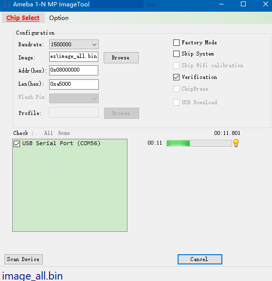
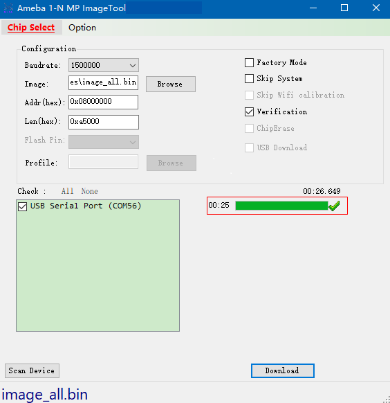
Image download is ok
Optional Functions
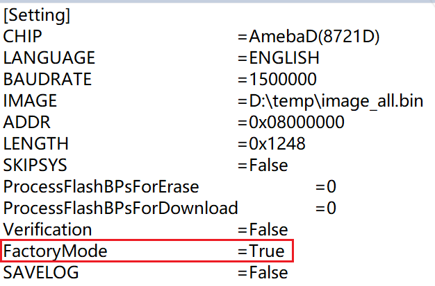
Factory Mode
The factory mode aims to disable some functions on the UI to avoid misoperated during the mass production.
Factory Mode
If Factory Mode is enabled, the UI disables some functions. The configuration parameters are saved to Setting.ini and reloaded when the tool restarts the next time.
There are two ways to exit the factory mode:
Close the tool.
Delete
Setting.ini.Edit
Setting.iniand modifyFactoryModeparameter value to False.
Parameters modification
Open the tool again, and the modified parameters will be restored to normal mode.
Verification
This option means whether to examine the checksum after download finished.
Method: Select checkbox Verification in step 3 in Download Flow.
ChipErase
This option means whether to erase chip before download.
Method: Select checkbox ChipErase in step 3 in Download Flow.
Skip System Data
This option means whether to skip system data area or not when downloading image.
Method: Select checkbox Skip System in step 3 in Download Flow.
USB Download
This option means whether to download image through USB COMx.
Method: Select checkbox USB Download in step 3 in Download Flow.
If this option is selected, click Profile Browse button to choose the target profile file.
Skip Wi-Fi Calibration
This option means whether to skip Wi-Fi calibration when downloading images.
Method: Select checkbox Skip Wifi calibration in step 3 in Download Flow.
Support for >16MB Flash Download
This option means whether support for >16MB Flash download. This function will help users program OTP bit to enable 4-byte mode to access the Flash.
Method: Select Option -> Support for >16MB Flash Download in step 3 in Download Flow.
Remember Flash Protection Process for Erase/Download
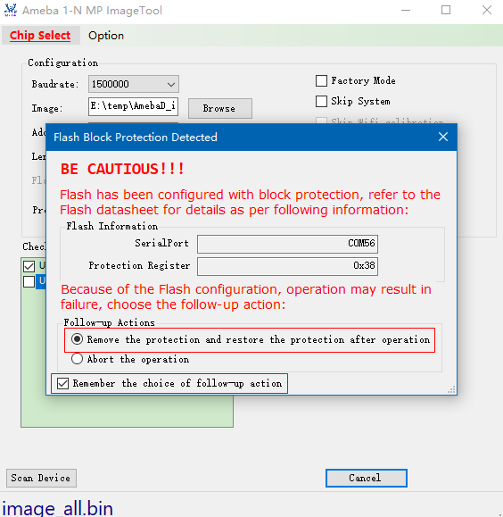
During the firmware-download process, the operation may fail because the Flash write-protection bit is set. When this happens, MP ImageTool pops up a dialog box that guides the user through the required corrective action. The tool then stores the chosen handling method so that, the next time Flash write protection is detected, it can automatically apply the same solution without further user intervention.
If the programming tool detects Flash write protection, the pop-up message appears as follows:
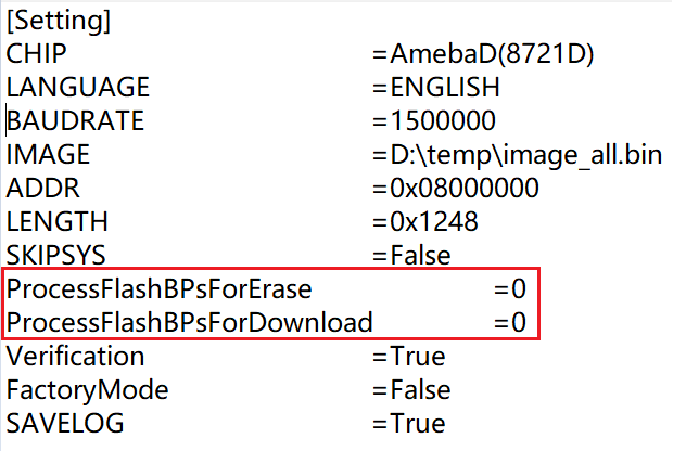
Alternatively, customer can preset the handling method in the
{MP ImageTool}/Setting.inifile by saving the parametersProcessFlashBPsForEraseandProcessFlashBPsForDownload. Doing so prevents download failures caused by mistaken choices on the production line during mass production.The two parameters mean the following:
1:Tool will remove the Flash protection and restore the Flash protection when erase/download.
2:Tool will abort erase/download when detect Flash block protection.
Method: Refer to Step3 in Download Flow and select Option –> Remember Flash Protection process for erase/download 。
If some typical troubleshootings occur, refer to Section Troubleshooting for help.
Command Line Mode
Download Flow
This tool can also work in command line mode. Start cmd.exe in Windows and execute Ameba_1-N_MP_ImageTool.exe with defined parameters, and the command line mode supports multi-parameters input with one command after v2.5.11.
The steps to download images in command line mode are as follows:
Set the configuration
Set the chip type
Use
-c/--chip [amebaz|amebad|amebaz2|amebasmart|amebalite|amebadplus]as parameters for target chip set.$Ameba_1-N_MP_ImageTool.exe -c amebaxxx CHIP: AMEBAXXX
Set the baudrate
Use
-b/--baudrate <value>as parameters.$Ameba_1-N_MP_ImageTool.exe -b 1500000 BAUDRATE: 1500000
Note
The value of baudrate only can be set as 115200, 128000, 153600, 230400, 380400, 460800, 500000, 921600, 1000000, 1382400, 1444400, and 1500000.
Set target image path
Use
-i/--image <image_path>as parameters to specified the target image.$Ameba_1-N_MP_ImageTool.exe -i E:\test\image_path\image_all.bin FILE PATH: e:\test\image_path\image_all.bin
Set download start address
Use
-a/--address <value>as parameters to specified the start address to program image.$Ameba_1-N_MP_ImageTool.exe -a 0x08000000 ADDRESS: 0x08000000
Set image length
Use
-l/--length <value>as parameters to specified the image size, it can be set 0x0 and tool will calculate the actual image size automatically.$Ameba_1-N_MP_ImageTool.exe -l 0xa500 LENGTH: 0XA500
Note
This parameter is necessary for download, if it’s empty, tool will load the value from setting.ini and the value may be not the actual image size.
Double check settings to download
Use
--show settingas parameters to check the tool configuration.$Ameba_1-N_MP_ImageTool.exe --show setting CHIP: AMEBAZ BAUDRATE: 1500000 IMAGE: e:\test\image_path\image_all.bin ADDRESS: 0x08000000 SKIP SYSTEM: False LENGTH: 0x0 ProcessFlashBPsForErase: 0 ProcessFlashBPsForDownload: 0 VERIFICATION: True SAVELOG: True
Note
The configurations need to be done only once before mass production (MP). These parameters would be saved into Setting.ini. When MP starts, the factory can download directly.
Download images
After configuration is finished, use
-d/--download <dev1>or-d/--download addedto download images for devices.-d/--download addedis used to download images for all devices specified by--add devicecommands.$Ameba_1-N_MP_ImageTool.exe -d added
-d/--download <dev1>is used to download images for a specified device without modifying the device list.$Ameba_1-N_MP_ImageTool.exe -d COM4 COM5 1 COM4 SUCCESS 2 COM5 SUCCESS
Note
After v2.5.11, the command line mode supports multi-parameters input when download starts.
$Ameba_1-N_MP_ImageTool.exe -c amebad -b 1500000 -a 0x08000000 -l 0xa500 -i e:\test\image_path\image_all.bin -s true -d COM4 COM5
1  COM4 SUCCESS
2  COM5 SUCCESS
Optional Functions
Scan Device
Use --scan device as parameters to check serial ports connected to PC.
$Ameba_1-N_MP_ImageTool.exe --scan device
USB Serial Port (COM4)
USB Serial Port (COM5)
After you execute this command, the terminal will list information about all currently connected serial-port devices.
Add/Remove/Show Device
In a production environment, you can streamline firmware-download operations by using MP ImageTool to lock in the device’s port settings.
Once the ports used on the production line are known, you can run the relevant commands to add or remove those ports in {MP ImageTool}/dev_config.txt.
After that, MP ImageTool will automatically detect and use the pre-configured ports, so you no longer have to specify them manually every time you issue a download command.
$Ameba_1-N_MP_ImageTool.exe --add COM4 COM5
COM4 added!
COM5 added!
$Ameba_1-N_MP_ImageTool.exe --show device
COM4
COM5
$Ameba_1-N_MP_ImageTool.exe --remove COM5
COM5 removed!
$Ameba_1-N_MP_ImageTool.exe --show device
COM4
If devices are added, the command to download is specified in step 4 in Download Flow.
USB Download
USB download is supported for NAND Flash image download. Set this option function in step 2 in Download Flow.
To select whether to use USB download or not, use -u/--usbdownload [true|false] as parameters.
True: enable USB download
False: disable USB download
$Ameba_1-N_MP_ImageTool.exe –u true
USBDOWNLOAD:    True
If USB download is selected, the profile should be set well, use -p/--profile <path> as parameters.
$Ameba_1-N_MP_ImageTool.exe –p E:\MP_Image_Tool\image_all.rdev
PROFILE:  e:\mp_image_Tool\image_all.rdev
Note
if USB download is enabled, the ports scanned with command --scan device are USB ports, otherwise are UART ports.
Verification
To select whether to examine the checksum after download is finished, use -v/--verify [true|false] as parameters.
True: enable verify
False: disable verify
$Ameba_1-N_MP_ImageTool.exe –v true
VERIFICATION:  True
This option function should be set in step 1 in Download Flow.
Chip Erase
The option
-e/--chiperase [true|false]determines whether the device’s Flash should be completely erased before the firmware download starts.
True: Enable Chip Erase
False:Disable Chip Erase
$Ameba_1-N_MP_ImageTool.exe –e true
CHIPERASE:  True
This option function should be set in step 1 in Download Flow.
The
--erase <address> <length> <dev1> <dev2>option is used in command-line mode to erase a specific address range of the device’s Flash memory.
<address>: Starting address of the Flash region to be erased, specified in hexadecimal format
<length>: Length of the Flash region to be erased, specified in kilobytes (KB).
<dev1> <dev2>: Port of target devices
$Ameba_1-N_MP_ImageTool.exe --erase 0x08000000 1024 COM56
Flash erase done!
Note
Before performing a Flash erase, make sure all related parameters are properly configured—for example, the firmware image, baud rate, and any other relevant settings.
DtrRtsConfig
If the device supports configuring DtrRts to enter UART download mode automatically, this option will help you. Use -g/--dtrrtsconfig [true|false] as parameters.
True: enable Dtr/Rts control
False: disable Dtr/Rts control
$Ameba_1-N_MP_ImageTool.exe –g true
DtrRtsConfig:  True
This option function should be set in step 1 in Download Flow.
Remember Flash Protection Process for Erase/Download
To select whether to remember Flash protection process for erase/download after erase/download is finished, use -f/--processflashbpsforerase | -n/--processflashbpsfordownload <value> as parameters.
1: Tool will remove the flash block protection bits and restore them when erase/download finished.
2: Tool will abort erase/download when detect flash block protection.
$Ameba_1-N_MP_ImageTool.exe –f 1
ProcessFlashForErase:  1
$Ameba_1-N_MP_ImageTool.exe –n 1
ProcessFlashForDownload:  1
This option function should be set in step 1 in Download Flow.
Save Log
To select whether to save log or not, use -s [true|false] as parameters.
True: enable save log
False: disable save log
$Ameba_1-N_MP_ImageTool.exe –s true
SAVELOG:    True
This option function should be set in step 1 in Download Flow.
GPIO/PWM Indication
The tool supports downloading image through USB for NAND Flash. Since the device and USB port do not have a unique correspondence, the download failed devices cannot be well identified on the production line. If you need to download image through USB, the GPIO/PWM indication function can be used to indicate which devices have successfully downloaded the images, so as to redo the download processes for the failed devices.
According to the configuration parameters, the tool will send the corresponding query to the device, and the device will output high or low level through GPIO or output PWM through PWM channel.
The configuration methods are shown below:
Turn off the running tool first.
Open the
Setting.inifile in the tool directory and configure theProgramConfig(default: 0).Refer to as following table for bit field description of
ProgramConfig.Bit
Description
[63:32]
Download indication configuration:
For GPIO indication
Bit[63:33]: Reserved
Bit[32]: GPIO output level
For PWM indication
Bit[63:57]: PWM duty cycle (0~100, unit: percent)
Bit[56:32]: PWM period (unit: us)
[31:30]
Download indication strategy:
0: Disable
1: GPIO indication after download success
2: PWM indication after download success
3: Reserved
[29:16]
Download indication PIN name, refer to the SoC-specific definition of PinName for MBED API
GPIO: all GPIO pins can be selected
PWM: PWM channels can be selected
[15:2]
Reserved
[1:0]
NAND Flash bit flip fail level:
2/3: Reserved
1: Fail at fatal bit flip error, i.e. bit flip count > ECC level
0: Fail at bit flip error, i.e. bit flip count >= ECC level
Save
Setting.iniand reopen the tool to download.
Read MAC
Read the MAC of the devices through the command -r/--readmac:
$Ameba_1-N_MP_ImageTool.exe -r COM4
COM4  FF-FF-FF-FF-FF-FF
Combine Images
Use --combine "<image1_path>;<image2_path>" --offset "<image1_offset><image2_offset>" [--output "<image_all_output>"] to combine the images together.
combine: image1_path, image2_path are means the images to be combined.
offset: image1_offset, image2_offset: the images’ offset that should be consistent order of imagex_path.
output: option parameter, specified the image_all.bin path, if empty, the combined image is located at the root directory of tool.
$Ameba_1-N_MP_ImageTool.exe --combine "E:\image1.bin;E:\image2.bin" --offset "0x00000000;0x00004000" --output E:\image_all.bin
Offset0: 0x00000000, Image0: E:\image1.bin
Offset1: 0x00004000, Image1: E:\image2.bin
Images have been combined successfully, size: 12KB, path: E:\image_all.bin
Erase
Use --erase <address> <value> [length] <value>(KB) <dev1> <dev2> to erase the Flash in CLI mode.
address: the start address to erase, hex format.
length: the size to erase, unit: KB.
dev1, dev2: target dut comx
$Ameba_1-N_MP_ImageTool.exe --erase 0x08000000 1024 COM56
Flash erase done!
Note
Before erasing the Flash, you should set up the device, such as setting the images, the baudrate, and so on.
CLI Help
The supported parameters can be achieved by typing --help.
$Ameba_1-N_MP_ImageTool.exe --help
Ameba 1-N MP ImageTool 2.5.13.0
Copyright ?  2016
-a ADDRESS, --address=ADDRESS                                                  Set start download address
-b BAUDRATE, --baudrate=BAUDRATE                                               Set download baudrate
-c CHIP, --chip=CHIP                                                           Set target chip
-d [COMx COMy COMn|added], --download=[COMx COMy COMn|added]                   Target device to download
-e TRUE|FASLE, --chiperase=TRUE|FASLE                                          Erase chip or not before download
-f PROCESSFLASHBPSFORERASE,
   --processflashbpsforerase=PROCESSFLASHBPSFORERASE                           Process flash BPs for erase or not when download
-g TRUE|FASLE, --dtrrtsconfig=TRUE|FASLE                                       Set Dtr/Rts config or not
-h FLASHPIN, --flashpin=FLASHPIN                                               Set flashpin for download
-i IMAGE, --image=IMAGE                                                        Set target image path
-k TRUE|FASLE, --skipsys=TRUE|FASLE                                            Skipsys or not when download
-l LENGTH, --length=LENGTH                                                     Set target image length
-m TRUE|FASLE, --support4bytesaddrmode=TRUE|FASLE                              Support 4-byte address mode or not when download
-n PROCESSFLASHBPSFORDOWNLOAD,
   --processflashbpsfordownload=PROCESSFLASHBPSFORDOWNLOAD                     Process flash BPs for download or not when download
-p PROFILE, --profile=PROFILE                                                  Set target device profile path for download
-r [COMx COMy COMn|added], --readmac=[COMx COMy COMn|added]                    Target device to read mac
-s TRUE|FASLE, --savelog=TRUE|FASLE                                            Save log or not when download
-t CheckFlashAddrModeTimeoutSecond,
   --checkflashaddrmodetimeoutsecond=CheckFlashAddrModeTimeoutSecond           Timeout(unit:s) used to pop confirmwindow for check flash address mode
-u TRUE|FASLE, --usbdownload=TRUE|FASLE                                        Select usb download or not
-v TRUE|FASLE, --verify=TRUE|FASLE                                             Set verification or not when download
-w TRUE|FASLE, --skipwifi=TRUE|FASLE                                           Skip wifi for AmebaZ2
--add=COMx COMy COMn                                                           Add target device
--remove=COMx                                                                  Remove target device
--combine=IMAGE1;IMAGE2;IMAGEx                                                 Combine images together
--offset=OFFSET1;OFFSET2;OFFSETx                                               Images' offset to combine
--output=OUTPUT                                                                Combined images output path
--erase=addr length COMx COMy COMn                                             Erase target device at addr with length(KB)
--show=setting|device                                                          Show setting or device
--scan=device                                                                  Scan devices
--help                                                                         Display this help screen
--version                                                                      Display version information
If the print message shows that the download procedure is failed, check the log file located at /log to get the fail reason.
Common Config
You can change the configuration in Setting.ini.
Note
Close the tool first before changing the configuration below.
Show Detail Log
This option aims to show the detailed logs for users. You can change the configuration in Setting.ini to select whether to show the detailed logs or not.
True: Enable show detail log
False: Disable show detail log
ShowDetailLog =True
This option function should be set in step 2 in Download Flow.
Download Progress Display
You can set the configuration in Setting.ini to select whether to show progress Bar in console when downloading in CLI mode.
True: Enable show download progress bar
False: Disable show download progress bar
DownloadProgressDisplay =True
This option function should be set in step 2 in Download Flow.
DTR/RTS Configuration
If the device supports automatically entering download mode via the DTR/RTS control module, you can enable this feature by configuring the DtrRtsConfig option in the {MP ImageTool}/Setting.ini file.
True:Enable DTR/RTS
False:Disable DTR/RTS
DtrRtsConfig =True
Download image to sram
After v2.5.24, Ameba 1-N MP ImageTool supports to download to sram with mp shrink image. The system will reboot automatically after download successfully and it can response to command through serial port without hard reboot.
And the mp image layout in sram is:
Image type |
StartAddress |
EndAddress |
|---|---|---|
km0_km4_app.bin |
0x2001A000 |
0x20080000 |
Image type |
StartAddress |
EndAddress |
|---|---|---|
kr4_km4_app.bin |
0x2001A000 |
0x20080000 |
Image type |
StartAddress |
EndAddress |
|---|---|---|
kr4_km4_app.bin |
0x2001A000 |
0x20080000 |
MP shrink image address setting
Automatic flashing solution
In practical applications of the Ameba module, situations may arise where it must automatically enter flashing mode or be forcibly restarted.
This section describes the solution implemented on the Realtek reference board that enables the SoC to enter flashing mode automatically.
Circuit design
The USB-to-UART converter chip used on the Realtek reference board is the PL2303GC. The circuit design is shown below and supports the two functions described above.
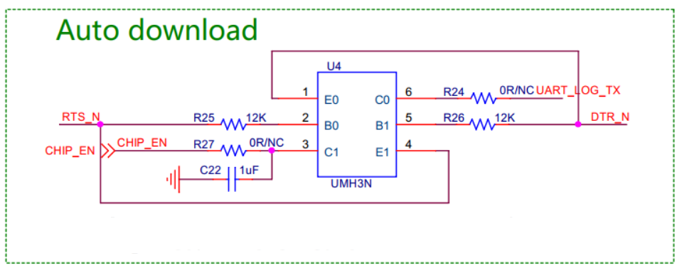
In the circuit above, the UMH3N contains two identical NPN transistors. The correspondence between the input and output signals is shown in the following truth table:
Input
Output
DTR
RTS
CHIP_EN
LOGUART_TX
0
0
1(EXT PU)
1(EXT PU)
1
1
1(EXT PU)
1(EXT PU)
0
1
1
0
1
0
0
1
Regarding timing, please note the following points:
The control logic for DTR and RTS is inverted with respect to the higher-level software logic; the corresponding chip-pin signals are named DTR_N and RTS_N. In other words, when the upper-level API sets the output to logic 1, the actual signal driven on the chip pin is logic 0. Therefore, remember to apply this inversion when developing the flow. The augmented truth table is as follows:
Windows API Control Input
Input
Output
DTR
RTS
DTR_N
RTS_N
CHIP_EN
LOGUART_TX
1
1
0
0
1(EXT PU)
1(EXT PU)
0
0
1
1
1(EXT PU)
1(EXT PU)
1
0
0
1
1
0
0
1
1
0
0
1
After inspecting all EVBs, we found that every board pulls CHIP_EN up externally, but an external default pull-up on LOGUART_TX exists only on the DP EVB.On boards without this pull-up, the TX pin becomes floating while CHIP_EN is held low.With the collector left floating, the associated transistor cannot source current and therefore cannot switch on correctly.When using this feature, you must populate an external 10 kΩ pull-up resistor on LOGUART_TX.
To enter DOWNLOAD MODE, TX must remain low for a short period after CHIP_EN goes high so the internal circuitry can latch the signal.CHIP_EN transitions from 0 → 1, meaning the corresponding transistor turns from ON to OFF; this rising edge is produced by the external pull-up resistor. TX transitions from 1 → 0, meaning its transistor turns from OFF to ON; this edge is driven actively by the transistor. To satisfy the timing requirement (TX already low when CHIP_EN goes high), slow the rising edge of CHIP_EN by adding a capacitor. On the EVB, a 1 µF capacitor is typically mounted by default.
After the chip has latched DOWNLOAD MODE, its internal logic takes over the LOGUART_TX pin after a brief delay, actively driving it high and low. To avoid bus contention, software must release control: once latching is complete, disable the transistor that was driving TX.
The timing described in point 4 above is influenced by the following factors:
Because a capacitor is connected to CHIP_EN, once RTS changes to 1, TX is pulled low immediately, whereas CHIP_EN is pulled low only after a short delay. With a 1 µF capacitor, the delay on CHIP_EN is roughly 10 ms. ——T1
The chip’s internal circuitry latches the TX value approximately 10 ms after CHIP_EN goes high. ——T2
he chip’s internal circuitry takes control of the TX pin roughly 40 ms after CHIP_EN transitions to a high level. ——T3
Therefore, after the software pulls RTS high, it must wait for a duration within the interval [T1 + T2, T1 + T3] before pulling DTR high. This timing both ensures the device latches into download mode, and releases software control of the TX line before the chip takes it over, preventing a short.
Timing
The recommended flow for Reset and Auto-Download is shown below. All configuration items referenced in the flow correspond to control signals defined in the Windows API and have already been translated once by an intermediate layer.
Automatic restart timing requirements:
DTR = 0
RTS = 1
DELAY 200ms
RTS = 0
DTR = 0
Timing requirements for automatic entry into burn (programming/download) mode:
DTR = 0
RTS = 1
DELAY 200ms
DTR = 1
RTS =
DELAY 35ms
Note
If the customer customizes any of the above timing sequences, they must contact the FAE to obtain a customized 1-N MP ImageTool version.
PL2303GC Driver Requirements
For different versions of Windows, the PL2303GC driver must meet the following minimum versions:
Windows 10: driver version ≥ 5.1.8.0
Windows 11: driver version ≥ 5.2.8.0
You can update the driver directly through Windows Update or download and install it from the official Prolific website.
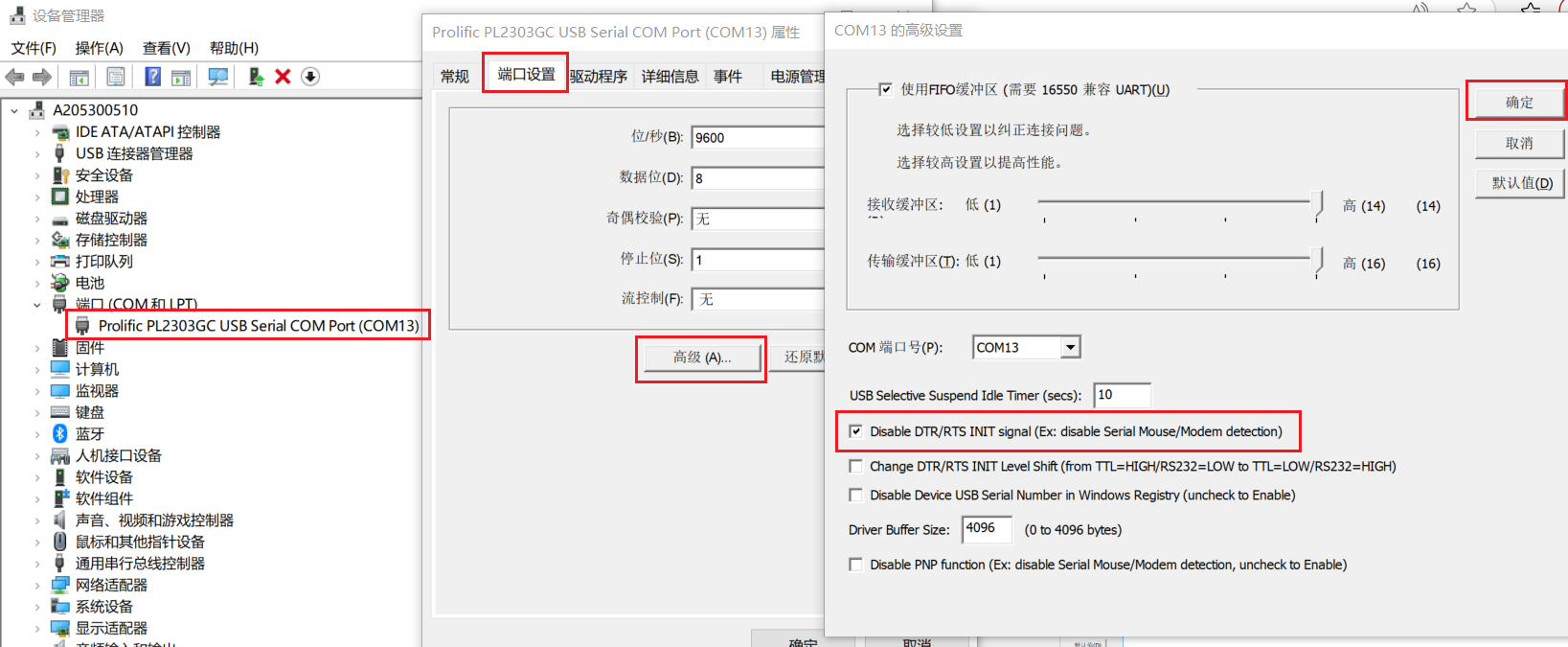
In addition, when a new USB device is plugged into the PC, Windows re-enumerates any idle USB devices that are already connected. During this enumeration the PL2303GC toggles its DTR/RTS lines, which can disturb the DTR/RTS state of devices already in use. To prevent this, you must disable the automatic DTR/RTS initialization:
Path: PL2303 Port → right-click “Properties” → “Port Settings” → “Advanced” → check “Disable DTR/RTS INIT signal”, then click OK to save.
Troubleshooting
Download Fail
If image download is failed, enter the UART_DOWNLOAD mode to try again.
When transmission interrupts or verification fails, a red error sign shows up, you need to check the error log and try again. There are two ways to get the error messages:
Hover the mouse cursor over the sign, the error message shows up, as following figure shows.
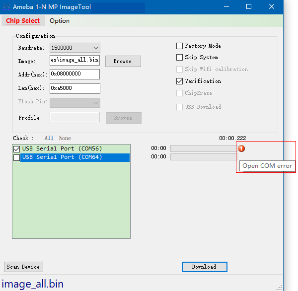
Download is fail
Check the log file which locates at
/log/to get more detailed error messages.Start Tool from UI Scan Device Start Scan Device End Start to Download... COM56 Open COM error
Note
Enable save log function first before download starts.
Flash Write Protected
If Flash is write protected by Flash BPs, that is to say, when Flash block protection is detected during image download or Flash erase, a pop up dialog will guide user to choose the follow-up actions.
You can process Flash BPs for download as needed, as following figure shows.
Flash block protection detected
Or set
ProcessFlashBPsForEraseandProcessFlashBPsForDownloadto process Flash block protection bits inSetting.inito avoid download blocked error.
The values of ProcessFlashBPsForErase and ProcessFlashBPsForDownload are:
0: When detect Flash block protection, tool pops new window to ask the customer what to do next when erase/download.
1: Tool will remove the Flash protection and restore the Flash protection when erase/download.
2: Tool will abort erase/download when detect Flash block protection.
Setting.ini
Power-off Accident
If accidents happen when transmission is in progress such as DUT powers off by accident, which cause the download failed, try to enter the UART_DOWNLOAD mode and download again.