Layout of DSP
Default Layout of DSP
We use a linker support package (LSP) to describe the layout of DSP. A LSP specifies object files to pull into an executable using a specific memory map, and is used as a convenient short-hand for telling the linker what it needs for a particular target environment. Refer to Xtensa Linker Support Packages (LSPs) Reference Manual (dspdoclsp_rm.pdf) for more information.
Here is the sketch of the default layout:

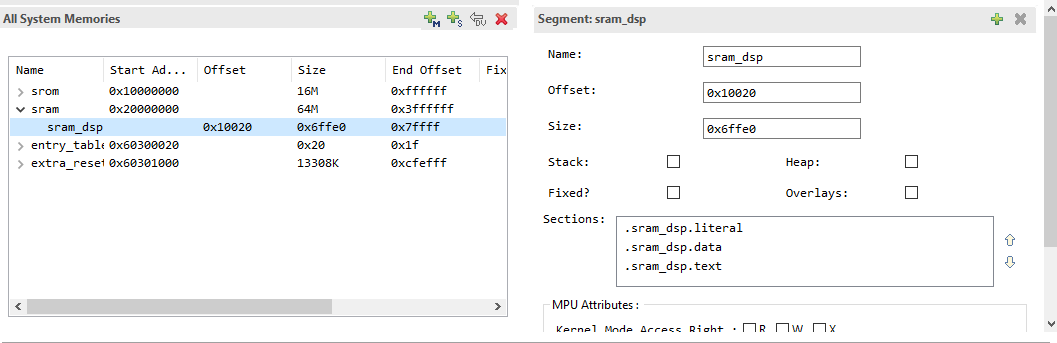
Here is the LSP seen from Xplorer:
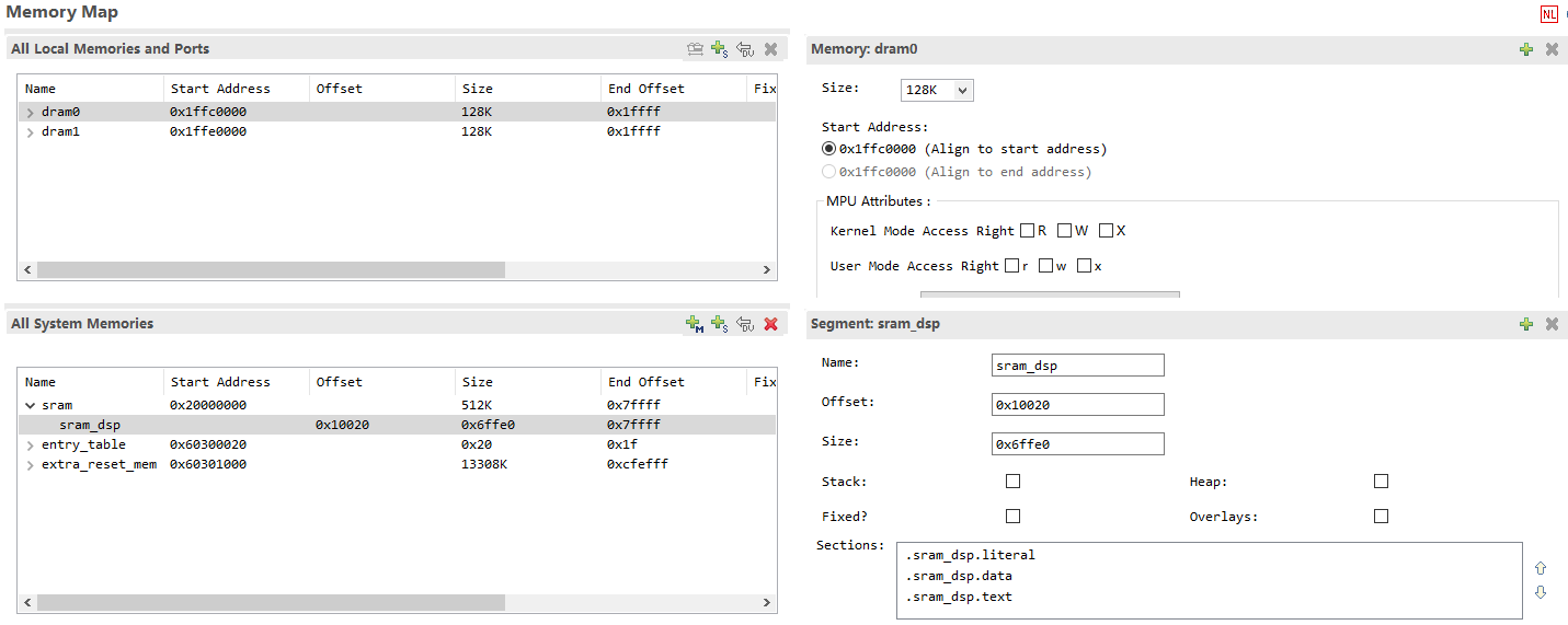
DSP can use sram_dsp, entry_table and extra_reset_mem for system memory, and DRAM 0/1 for local memory. Reset vector address will be placed in entry_table. DRAM 0/1 can only be used to store data.
For Call0 ABI, code AND data can be stored in sram_dsp and extra_reset_mem.
For Window ABI: code can only be stored in extra_reset_mem, data can be stored in sram_dsp and extra_reset_mem.
Placing Codes/Data into SRAM
There is a segment called sram_dsp in the default LSP: RTK_LSP. Putting codes or data into this area may have an effect on the performance of the whole project.
Using C Language Extensions
If the function to be placed into SRAM is:
void place_into_sram();
You should do this:
extern void place_into_sram()__attribute__ ((section(".sram_dsp.text")));
void place_into_sram(){
  //detailed implentation
   }
If you need to put an array into SRAM, you can do like this:
__attribute__ ((section(".sram_dsp.data"))) int array_in_psram[100];
Compiler Flags to Rename Sections
If all functions in
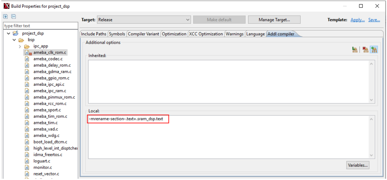
ameba_clk_rom.cneeds to be placed in SRAM, right click on this file, and chooseBuild Properties. And in the new window, set values to No for items in the box.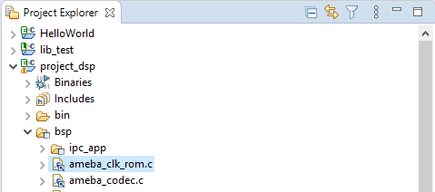
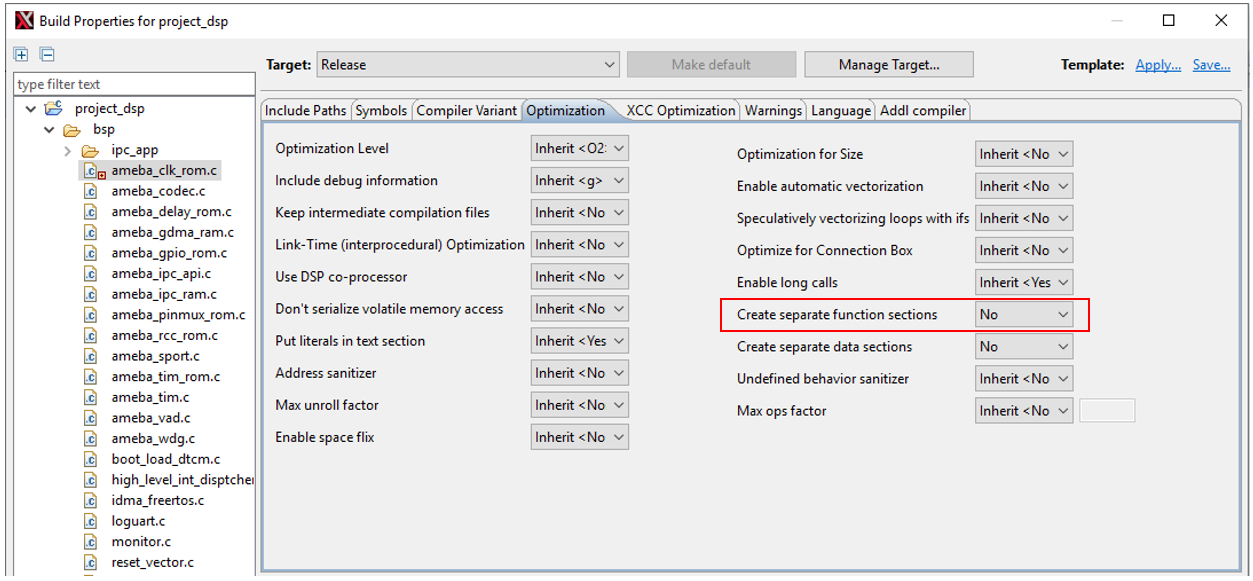
Switch to Addl compiler tab, add an option as follows:
Changing Default Layout of LSP
MCU and DSP share the PSRAM and SRAM, but DTCM is exclusive to DSP. When the layout of MCU changes, the LSP of DSP should change accordingly. For DSP memory layout, the memory addresses of DTCM and SRAM generally remain default, and only the start and end addresses of PSRAM need to be adjusted. We only need to use a python script to adjust the PSRAM space of the DSP, and then modify the MCU layout file accordingly according to the output of the script. The specific operation method is as follows:
Enter the directory:
{SDK}\project\img_utilitycd {SDK}/project/img_utility
With the command
python lsp_modify.py, you can get the current DSP PSRAM address from output:>> python lsp_modify.py Current LSP psram: Start Address: 0x60300000, End Address: 0x61000000, Size: 0xd00000 Invalid input. Please enter the start and end addresses in hex. Example: "python lsp_modify.py 0x60300000 0x61000000" DSP link script change FAIL.
With the command
python lsp_modify.py <start address in hex> <end address in hex>, you will get a new lsp:>> python lsp_modify.py 0x60400000 0x60A00000 Current LSP psram: Start Address: 0x60300000, End Address: 0x61000000, Size: 0xd00000 New LSP psram: Start Address: 0x60400000, End Address: 0x60a00000, Size: 0x600000 Warning : 'entry_table' start address not aligned to MPU min alignment (is 0x60400020, min alignment is 0x00001000) Warning : MPU region size smaller than min region size (0x60400020 - 0x60400040, is 32 must be at least 4096 bytes) Warning : 'unused' start address not aligned to MPU min alignment (is 0x60400040, min alignment is 0x00001000) New linker scripts generated in ../../project/RTK_LSP/RI-2021.8/HIFI5_PROD_1123_asic_UPG/RTK_LSP/ldscripts Change MCU layout (amebalite_layout.ld) PSRAM_DSP_START to 0x60400000
In the example, we adjust the PSRAM start/end positions to 0x60400000/0x60A00000. Since the MPU table automatically generated by the script, the address alignment warning above can be ignored without any adverse effects.
Add KEEP in the link script
RTK_LSPldscriptself32xtensa.x:.ipc_table : ALIGN(4) { _ipc_table_start = ABSOLUTE(.); KEEP(*(.ipc_table)) . = ALIGN (4); _ipc_table_end = ABSOLUTE(.); } >psram0_seg :psram0_phdr .command : ALIGN(4) { _command_start = ABSOLUTE(.); KEEP(*(.command)) . = ALIGN (4); _command_end = ABSOLUTE(.); } >psram0_seg :psram0_phdr
Change the layout file ({SDK}amebalite_gcc_projectamebalite_layout.ld ) according to the output of the script:
#define PSRAM_DSP_START (0x60400000)Recompile the DSP and MCU projects.
Note
Before using the script, make sure the bin directory of Xtensa tool has been added to the system or user path. Otherwise the executable file cannot be found. This script needs python3.
If you changed other MPU properties, please synchronize previous modifications on the newly generated
mpu_table.c. And compile the newmpu_table.cin the project.